
For my review, click HERE
22 March 2024: As noted in the original post, an early F8U-1P would require a Vought ejection seat and different wheel hubs than provided in the F8U-1P/RF-8A kit. Modification of the kit seat headrest would probably suffice for the former but exquisite 3D-printed replacement wheels are now available for the latter from Jonathan Smith.

Note that the openings in the nose wheel hub should line up.

Smith's main landing gear inboard main landing gear hubs do not include the disc-brake caliper assemblies that are located on the bottom of the landing gear strut but these are easily added.

They are provided on the kit wheels and correctly pictorially oriented if you're paying attention to the instructions:

22 January 2024: This is a work in progress. I'm still making additions and corrections. Please don't hesitate to inform me at tommythomason@sbcglobal of any you have.
This post has benefited significantly from input from Ed Barthelmes and Bill Spidle, who I consider to be Crusader subject-matter experts. For more on this iconic carrier-based airplane, I recommend you add Ed's F-8 Crusader Walk Around Number 38 from squadron/signal publications and Bill's Vought F-8 Crusader from Specialty Press to your library.
Finally, a 1/72 kit of the photo-reconnaissance F8U/F-8 Crusader! And the first impression before building it is excellent (Sword was also provided with pretty good Vought drawings of it). This is Sword's test assembly as an RF-8G"+":

To answer the two most frequently asked questions: there is no option to raise the wing and while some of the detail parts like the nose landing gear resemble that of the Academy F-8E/F-8E(FN), F-8J kit (Tom Weinel's preference: see https://superheatmemorial.blogspot.com/2018/12/172nd-f-8-kit-review.html), it is also clearly different in most particulars. One small flaw that Tom noted in most F8U kits (Heller got it right) that Sword also included: there is no fairing or bulge on the upper wing surface at the wing fold joint on any Crusader.
Pictures of the sprues and decals are here: https://aeroscale.net/news/crusader-box-contents. Note that there is no difference in the kits with respect to the plastic, resin, or even instructions. The only difference is the decal sheet. Additional markings will be forthcoming from Caracal Models. Also, don't lose track of the small rectangular tan piece of paper in the box. Barely perceptible on it are the masks for the canopy, windscreen, camera ports, and the view-finder window.
You may wonder, as I did, about the raised rounded triangles on the top of the inboard leading edge slat;

Bill Spidle informed me that these were associated with the F-8L wing which added pylons, one on each side, to F-8B wings. They were located at the hinges of the leading edge flaps and increased the fatigue life of the wing. After the F-8Ls were retired, their wings still had life remaining to they were utilized for at least some RF-8G upgrades. They are present on the RF-8G "+" BuNo 146882 on display at the Frontiers of Flight Museum in Dallas, Texas. His photo:

The F8U-1P prototype (a conversion of F8U-1 BuNo 141363) first flew on 15 December 1955. The last flight of one, an RF-8G"+", was to the National Air and Space Museum on 29 March 1987, over 30 years later. There were numerous detail changes to the configuration over that time. Sword provides most of them in this kit.
There were three basic versions, not counting details like DECM antenna fairings and camera ports:
F8U-1P/RF-8A: The most notable omissions from the kit are that the first F8U-1Ps were delivered with a Vought ejection seat, a nose-wheel hub with spokes, and a fuel vent mast under the left hand side of the aft fuselage. For the seat and nose wheel, see https://tailspintopics.blogspot.com/2009/10/f8u-crusader-variations.html. For more on the landing gear changes, see https://superheatmemorial.blogspot.com/2018/12/f-8-landing-gear.html. The kit only provides a Martin Baker seat that might be either a Mk 5 or a Mk 7. However, in 1/72 scale, these can be distinguished by painting the parachute housing accordingly (see http://thanlont.blogspot.com/2011/02/transition-to-martin-baker-ejection.html). For an introduction to the F8U-1P, click HERE.
RF-8G: 73 RF-8As of the original 144 were remanufactured to be RF-8Gs, including new wings that added a pylon on each side. These were delivered between 1965 and 1970. The most obvious external change was the addition of the ventral fins under the aft fuselage to increase supersonic directional stability (the left fin incorporated the RF-8A's fuel vent mast). For some reason, five USMC RF-8As got the ventral fins with no designation change. The G changes included a beef up the landing gear; the differences might not be readily apparent in 1/72 scale (see the landing gear link above). The tail hook shank went from squarish to round (the kit's looks squarish, i.e. RF-8A).
RF-8G"+": The + is a notation that Tom Weinel added to differentiate it from the G's that were modified to this configuration beginning in 1978. The major external difference was the addition of the cooling scoops on the top of the tail pipe and blocking off one of the small vents on the right side of the fuselage just ahead of the wing. For more on the afterburner differences, see https://superheatmemorial.blogspot.com/2018/12/f8u-engines.html
For more general background, see: https://tailspintopics.blogspot.com/2013/12/photo-gator.html. One comment on it by OldGeezer should be noted when evaluating the usefulness of the following:
From 1975-1977, I was one of the tiny group of engineers responsible for the last 30 or so RF-8Gs at the Naval Air Rework Facility in Norfolk. A lot of things stick in my mind, probably of no interest to anyone these days. You mention the ECM antennas, from memory the last ones I personally saw were Air Frame Changes 598 and 599. I don't think any two of the aircraft that came into our shop ever had identical antenna configurations, and we'd incorporate everything they had missed along with the latest stuff, so theoretically they'd leave our line all with the same equipment. That didn't apply to the cameras though. There were different numbers and locations of windows on the various airplanes, and we couldn't do much about that.
Which DECM antenna configuration you use can only be established by reference to the RF-8 that you are representing.
The first one on at least a few RF-8A/Gs as early as 1966 is the same as on the Crusader fighter of that era:
 |
The second one looks like this:

It uses parts 27, 28, and 30. It appears on Gs in pictures dated 1967 through 1972.
The next one deleted the antenna on the leading edge beginning in 1969. The trailing edge fairing extended farther forward on the fin (the tail light was embedded in the fairing) and there appears to have been two different fairing and antenna configurations. One had multifaceted lumps and appears to have been retained for the remainder of the RF-8's service life:

It resembles kit parts 57/58. I'm not sure when the flare/chaff dispensers were added under the fuselage aft of the main landing gear (they are not provided in the kit, either):

The other was shaped like a bullet and the fairing extended the farthest forward. It may have actually preceded the one described immediately above.

This would be kit parts 65/66.
Finally, an antenna was eventually scabbed onto the right hand underside of the G inlet.

The F8Us did not originally have red anti-collision lights on the top and bottom of the fuselage (they were not a requirement on U.S.civil airplanes before 1957; the military was not required to incorporate them but did). The upper one is provided as a separate clear part. The lower one is molded with the bottom of the camera bay, part CP2, and will have to be removed for the initial F8U-1P configuration.
The photoflash cartridge dispensers, one on each side of the upper fuselage aft of the cockpit, are usually covered by a panel that was removed when required for night missions (for illustrations of previous Navy photo flare dispensers, click HERE).
An F8U-1P with the small-diameter flare dispenser:

An RF-8G with the large-diameter flare dispenser:

Photo via Ed Barthelmes
The F8U-1P/RF-8A camera system:

Above the light detector window was one of two sensors, either a light monitor for day photos or a flash detector for night photos. The scanner window provided a view for the image motion sensor.
The RF-8G camera system was initially identical to the RF-8A's but eventually diverged. Note the removal of the Station 2 windows from the side and bottom of the fuselage and the addition of a prism window (kit part CP9) at Station 2 on the right side of the bottom of the fuselage. A second prism window was sometimes substituted for the Station 4 window on the bottom of the fuselage. Note that this airplane did not have the Doppler antenna or the single large DECM antenna fairing (see next photo for both) between the main landing gear doors in place of the two in this photo.

This is the bottom of a late RF-8G"+", mainly distinguished by the addition of DECM antenna variations (kit parts 25 and 70) and a Doppler antenna (molded with the bottom of the camera bay, part CP2, so it will have to be removed when modeling earlier aircraft configurations):

I'm not sure why the scanner window appears to be missing in this photo.
The presence or absence of the left or right Station 2 windows on Gs and G"+"s is another mystery. The left window is often missing with or without the prism window present on the bottom of the fuselage. However, the right window is sometimes present even though the left window is not.
Build Notes
There are holes on the inside of the fuselage halves that would need to be drilled out if you are adding the ventral strakes, which are mounted at a 45° angle. The kit parts have different part numbers but I don't know yet if they are actually handed.
Note that the wings were mounted with anhedral of 5 degrees and the horizontal stabilizers, dihedral of 5.4 degrees (n.b. the left and right UHTs were not connected):

Because of the length of service of the photo Crusaders (the high-time one was retired with almost 7,500 hours after 28 years and 11 overhauls) and Sword's reliance on close examination of survivors, there are mid-life and late-life detail additions on the kit parts like reinforcing doublers around the main landing gear wells and a small bulge above and below the stabilizer at its attach point to the fuselage that aren't present on the initial F8U-1Ps.
More to come...
Actually, I have written about this more than three times. Some unnumbered ones were:
Mk 4 Atomic Bomb: https://tailspintopics.blogspot.com/2011/07/getting-it-right.html
F11F Tiger: https://tailspintopics.blogspot.com/2014/10/f11f-tiger.html
P/F-80 Canopy: https://tailspintopics.blogspot.com/2013/10/lockheed-pf-80.html
A4D-2 Skyhawk: https://tailspintopics.blogspot.com/2012/07/new-airfix-172-4b4p-modeling-notes.html
F4D Skyray Wheels: https://tailspintopics.blogspot.com/2015/07/its-not-that-easy-to-avoid-error.html
J79 Exhaust Nozzles: https://tailspintopics.blogspot.com/2012/12/j79-exhaust-nozzles.html
Grumman F9F-8T Nose Strut Extension: https://tailspintopics.blogspot.com/2014/06/grumman-f9f-8ttf-9j.html
Numbered ones:
Part One (F6U): https://tailspintopics.blogspot.com/2017/06/relying-on-museum-examples-for-detail.html
Part Two (F7U-3M): https://tailspintopics.blogspot.com/2017/08/relying-on-museum-examples-for-detail.html
Part Three (AD Skyraider Vertical Fin: note that in this case, the fin shape of readily available examples has almost always been ignored): https://tailspintopics.blogspot.com/2017/08/relying-on-museum-pieces-for-accuracy.html
This post was inspired by the F11F kit project at DBMK (https://dbmk.co.uk/); also see their Facebook page. Note that their research includes LIDAR scans of an F11F.
Based
on their requests and questions, I can vouch for their desire for
accuracy, at least in this instance. The latest one was about this
feature under the forward fuselage between the forward speed brake and
the NACA air inlets.

I'd never noticed it before but quickly tracked this example down to BuNo 141735, now at the Yanks Air Museum at Chino, California. At first, I assumed it was for the attachment of an antenna that wasn't present, probably specific to this particular Tiger since it wasn't evident in pictures of any operational or Blue Angels F11Fs. I finally found one that wasn't BuNo 141735 with a shape there that seemed familiar:

More searching and I found a few more examples of Navy Training Command F-11s with the shape, in particular this one:

That's when the light dawned (no pun intended). At some point after the collision between two airliners over the Grand Canyon in June 1956, the CAA/FAA decreed a requirement for anti-collision lights on U.S. civil aircraft. The military was not required to comply but did so voluntarily. As a result, anti-collision lights were eventually added to the Navy Training Command's surviving F11Fs, including the early ones.


The external appearance of the McDonnell F-4B changed in detail during its time in service. This is not a comprehensive list of the changes to a kit required to reverse it to the configuration when it was first deployed on Enterprise in 1962.
1. Early Bs did not have the slotted stabilizer: http://tailspintopics.blogspot.com/2011/09/f-4-flapstabilizer-change.html
2. Early Bs did not have the bump on the upper surface of the wing over the main landing gear strut or the doubler reinforcement plates on the lower surface of the wing.
3. Early Bs had the Mk 5 ejection seat; the difference in the top of the seat is apparent in any scale: http://thanlont.blogspot.com/2011/02/transition-to-martin-baker-ejection.html
4. The initial external drop tanks on the wing were a McDonnell design; the Navy subsequently procured the cheaper Sergeant Fletcher tanks with a constant-diameter mid section (statements reversing the identification of the source of the tanks are wrong): https://tailspintopics.blogspot.com/2014/02/f4hf-4-370-gallon-external-tank-redux.html
5. The total air sensor wandered around from the nose to the vertical fin and back: https://tailhooktopics.blogspot.com/2022/07/mcdonnell-f4h-total-air-temperature.html
6. Initially the only external antenna was on the nose landing gear door:

7. Deliveries of the IR sensor under the radome were behind schedule and the performance of the system when it was available, a disappointment, so it was usually not present, replaced by a cap.

When present, the portion immediately behind the dome was probably cylindrical rather than tapered as in the picture above.

The dome of the AN/AAA-4 sensor is reflective, essentially a mirror.
8. There were detail changes to the cockpit over time but with the exception of the top of the Mk 5 vs. Mk 7 ejection seat in any scale and the instrument panel/radar control in aft cockpit in 1/32, I doubt that they would be discernible by the casual observer. Bill Spidle provided the following illustrations for the Block 22 configuration (circa 1966), BuNo 152244 and subsequent, at least for a while:


Note that the radar scope in the rear cockpit retracted under the instrument panel and the black on either side of the upper part of the instrument panel were curtains (there was also one that blocked out light overhead).

9. One detail missed by most kit designers is that the aft bulkhead of the rear cockpit was never slanted. It was vertical (the compartment was not originally intended to be occupied) and the ejection seat rails were attached to the floor and the top of the aft bulkhead so as to be at the correct angle.

10, The wingtip lights:

The Skywarrior bombers had a self-boarding arrangement* that also did double duty as a bailout slide:
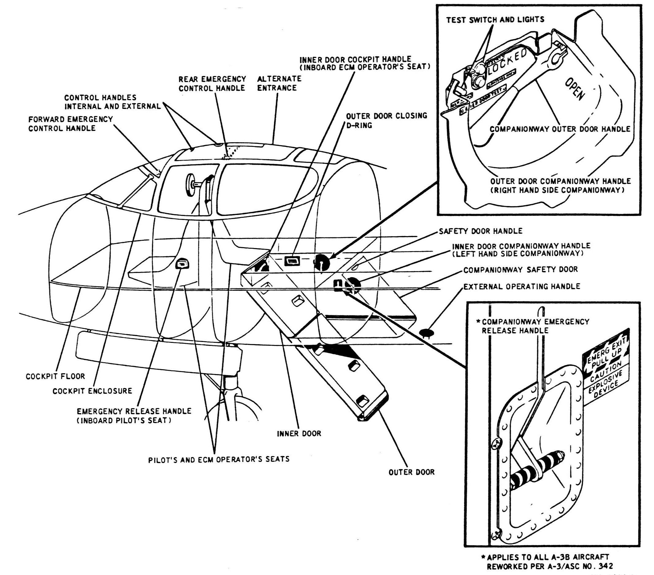
It consisted of an inner (upper) and outer (lower) door. When closed, the inner door formed the bottom of the cockpit floor and sealed the crew compartment for pressurization; the outer door closed off the opening in the bottom of the fuselage. Large indentations, two in the inner door and three in the outer door, served as steps and hand grips and still allowed the doors to have a smooth surface to function as a slide for bailout.

However, the following picture of a crewman ascending into the cockpit included a feature not included in the illustration above, a rectangular transverse ledge (highlighted by question marks) with a raised non-skid pattern.

On close examination (you can see successive ledges below the top one), I finally realized that in this instance, climbing into the airplane had been made easier—particularly if you had something in your hands—by leaning a folding ladder up against the outer door.

* Skywarrior versions had similar arrangement that was different in detail, including the arrangement of steps:

Also see http://tailspintopics.blogspot.com/2013/05/trumpeter-148-a3d-forward-fuselage.html).
2 September 2023: Added an illustration of how the nose gear shock strut functioned.
7 June 2024: Added Mk 7 and Mk 8 Control Panels
This post incorporates material provided from the Greater St. Louis Air and Space Museum by Mark Nankivil.
Click HERE for my previous post on the "Nuclear Banshees". When I get a chance, I'll correct some of the discrepancies in it. Click HERE for my F2H Banshee Modeler's Notes: it includes links to several of my other posts on the Banshee.
By the early 1950s, the Mk 7 and Mk 8, tactical nuclear weapons small enough to be carried by single-seat fighters and bombers, had been developed. The U.S. Navy quickly modified two carrier-based airplanes to accommodate them, the Douglas AD Skyraider (see http://tailspintopics.blogspot.com/2022/04/ad-4-skyraider-variant-ad-4b.html) and the McDonnell F2H Banshee. The suffix B was added to the designation of these airplanes to identify them as having non-standard armament.
The Mk 7 was lighter (about 1,680 lbs) than the Mk 8 (about 3,250 lbs) but much larger (30.5 inches in diameter and 182 inches long). To fit it under the inboard wing of the F2H-2 required that the landing gear shock struts be pressurized to extend them to their full travel.
The nose landing gear extension;

With the help of Jerry Wells, I was finally able to establish how the nose landing gear shock strut extended:


The result increased the height of the requisite pylon above the ground by 10 inches, providing just enough clearance for a carrier launch with a Mk 7:


(For a dimensioned drawing of the Mk 8, see the AD-4 link above.)


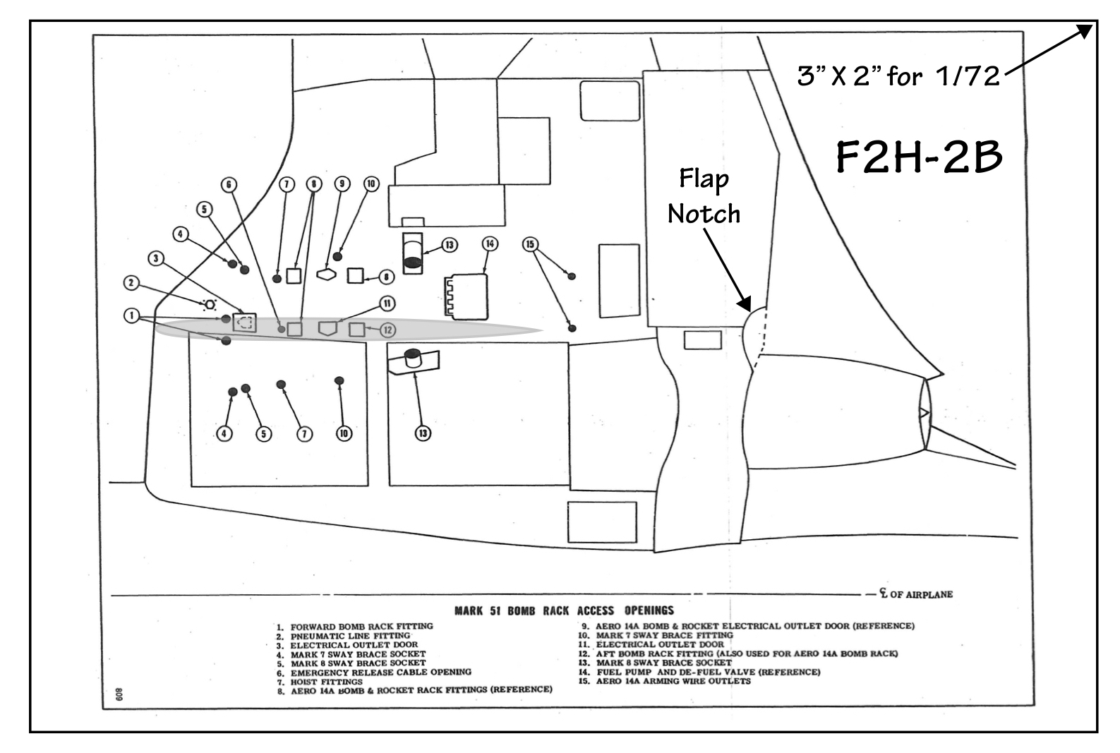
It was essentially coincident with the outboard edge of the engine intake opening:

Note that this initial capability predated the development of the Low Altitude Bomb System (LABS) delivery (click HERE). Instead, the bomb was to be dropped from altitude, in this example in a dive utilizing a "loft" bomb deliver capability, not to be confused with the loft options provided by LABS,

The flight manual advised caution not to exceed G limits when the Mk 7 was released in the loft maneuver; use of loft delivery for the much heavier Mk 8 was prohibited.
A couple of details on the Mk 7 development:
Problems with its stability and trajectory were discovered during initial test drops. This was solved in part by adding wedges one one side of the tips of the tail fins that resulted in the bomb spiraling like a football.

Another was the initial use of barometric pressure to provide an air-burst capability for more wide-spread devastation. However, as the Mk 7 neared the ground, it was going faster than the measurement of the air pressure could keep up with from a detonation accuracy standpoint. As a result, speed brakes were initially provided between the tail fins that opened up when the bomb was dropped (it probably also provide a few vital seconds for the pilot to get far enough away to avoid getting "hoist by his own petard").

Note that the Mk 8 did not have speed brakes because its raison d'etre was destruction of well-protected submarine shelters, accomplished by not detonating until as far below ground as possible, which meant that the faster it was going when it hit the ground, the better.
The development of bespoke pylons (to be described in a subsequent post covering the F2H-3/4 nuclear-strike configuration) and more options for changing the angle of the tail cone allowed the Mk 7 to be loaded with the fins pointed upwards and eliminated the separate sway braces required for the Mks 7 and 8.
An important feature of the F2H-2B was the addition of the newly developed inflight refueling capability. This was accomplished by adding a fuel probe replacing one of the 20mm cannons on the right side of the fuselage.

Only the fuselage fuel tanks could be refilled in flight, probably because these early jets did not have single-point refueling capability. Also filling the tip tanks would have required the addition of additional fuel lines and flow management valves and controls. That was a tradeoff against the extra range that would be achieved, particularly since even though the store was mounted fairly close to the center line, the tip tank on that side could only be partially filled before takeoff since only so much lateral imbalance could be offset by the roll-control power (i.e. aileron effectiveness) available at low speeds. At cruise speeds, however, the imbalance could probably be accommodated, albeit at some increase in drag due to the control-surface deflection.
The early refueling probe had a tip that resembled a baby bottle nipple. It was subsequently replaced by the one that's now standard across U.S. and NATO probes.

In any event, the F2H-2Bs were deployed in both "composite" squadron detachments and fighter squadrons:

This squadron's markings in color and regrettably, a bit out of focus:

The management of the store (arming, etc) was provided by a panel mounted on the right side of the cockpit above the console. Which panel was used depended on whether a Mk 7 or Mk 8 being carried.
Mk 7

Mk 8


