Sunday, October 23, 2011
F3H Beaver Tails
I've updated the F3H entry with pictures and an illustration of the two different beaver tails and also a picture of the two 20 mm cannon modification: http://tailspintopics.blogspot.com/2010/11/f3h-demon.html
Wednesday, October 19, 2011
Yankee Tractor Rocket Escape System
The retrofit of the Air Force A-1 Skyraiders, both single seat and wide body, with the Stanley Aviation Corporation Yankee escape system is fairly well known. As it turns out, this was a Navy initiative and at least two squadrons had their aircraft modified with this capability, VA-25 (Coral Sea) and VA-152 (Oriskany). It is properly described as an extraction system as opposed to an ejection seat, since the seat stays in the aircraft and the pilot is pulled out by the rocket as opposed to being pushed out.
VA-25

VA-152

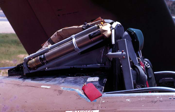
The retrofit was fairly simple. VA-25 reportedly had all 12 of its aircraft modified midcruise in a couple of weeks at NAS Cubi Pt, Philippine Islands in November 1967 while Coral Sea was off the line. It basically consisted of a rocket located under the canopy behind the pilot's head and a different seat/headrest. The rocket was connected to two ten-foot lines that were attached to the pilot's parachute harness.

The rocket was installed to the right of the existing canopy actuation mechanism.
 (Note that this mechanism was usually covered by canvas before the Yankee seat was installed.)
When the pilot activated the system by pulling a D-ring located between his thighs, the canopy was jettisoned and the rocket tilted upward and fired, extracting the pilot out of the cockpit. This is a test using a civil-registered T-6G.

 The system was rated for zero airspeed and zero altitude but only with zero sink rate and zero pitch/roll. A zoom climb was therefore recommended before jettisoning the airplane.
Although light weight, the extraction concept was most appropriate at the relatively low speeds usually attained by propeller driven aircraft although Stanley did sled tests at high subsonic speeds (see YouTube link below).
For more stuff on the Yankee seat, see:
http://skyraider.org/skyassn/otherpics/cole/Yankee.jpg
http://skyraider.org/hook/dashonet/yankee.htm
http://users.bestweb.net/~kcoyne/frame_sg.htm (Click on the Stanley "Yankee" button well down in the left column )
https://www.youtube.com/watch?v=8Yw8g1Soigk
For a comparison with the original seat, see http://tailspintopics.blogspot.com/2013/11/ad-1-skyraider-standard-vs-extraction.html
VA-25

VA-152

The retrofit was fairly simple. VA-25 reportedly had all 12 of its aircraft modified midcruise in a couple of weeks at NAS Cubi Pt, Philippine Islands in November 1967 while Coral Sea was off the line. It basically consisted of a rocket located under the canopy behind the pilot's head and a different seat/headrest. The rocket was connected to two ten-foot lines that were attached to the pilot's parachute harness.

The rocket was installed to the right of the existing canopy actuation mechanism.

When the pilot activated the system by pulling a D-ring located between his thighs, the canopy was jettisoned and the rocket tilted upward and fired, extracting the pilot out of the cockpit. This is a test using a civil-registered T-6G.


Although light weight, the extraction concept was most appropriate at the relatively low speeds usually attained by propeller driven aircraft although Stanley did sled tests at high subsonic speeds (see YouTube link below).
For more stuff on the Yankee seat, see:
http://skyraider.org/skyassn/otherpics/cole/Yankee.jpg
http://skyraider.org/hook/dashonet/yankee.htm
http://users.bestweb.net/~kcoyne/frame_sg.htm (Click on the Stanley "Yankee" button well down in the left column )
https://www.youtube.com/watch?v=8Yw8g1Soigk
For a comparison with the original seat, see http://tailspintopics.blogspot.com/2013/11/ad-1-skyraider-standard-vs-extraction.html
Thursday, October 6, 2011
AD Skyraider Modeling Notes
I was excited to read about Aero Research's new product, Modelers' Guide to the Skyraider by Jay Sherlock.
 20 April 2022 Update: Jay has now published a second edition that includes some of the material that I mention below that was missing from the original one. It costs $21.95 with shipping to the United States. For a description and to order, see http://www.aeroresearchcds.com/book_shelf.htm
I am very pleased with the content based on a quick read through. Jay has done a great job of delineating the differences between the several variants of the Skyraider and the plastic kits that represent it. However, it is not comprehensive, particularly with respect to the interior and photo coverage of details. For that, I recommend that you supplement it with the excellent Walk Around A-1 Skyraider by Ed Barthelmes and Richard S. Dann.


 The stick on one of the pylons is the strut to brace the wing when it is folded.
He also mentions the presence and absence of nose flaps, but unless I missed it, again you're on your own. There were six slightly curved segments that were hinged on the circumference of the cowl ring so they could be folded back along the interior of the cowl. When they closed off the cowl ring, they shortened the time needed for the engine to warm up, as indicated by the oil temperature. I also think they kept the engine cylinders from over-cooling when dive bombing.

There was a cutout in the upper inner edge of the flaps at the two and ten o'clock position, presumably to clear the magnetos on the nose case when the nose flaps moved between the open and closed positions, and a small triangular gap at the inboard side of the other flap corners.

Dave Cantrell provided the following photo of an AD cowl with the nose flaps open.

Note the "pin" indicator for nose-flap position sticking out of the cowl at 11 o'clock looking aft. There was a single cockpit spring-loaded switch for both cowl and nose flaps - open/off/close. They automatically went full open after touchdown via a landing gear squat switch. The cowl and nose flaps could be closed after shutdown with the cockpit switch overriding the squat switch. However, they all went full open the next time electrical power was applied, as on engine start. The nose flaps closed after the cowl flaps were fully closed and opened fully before the cowl flaps started to open. The nose flap indicator on the cowl ring stuck out the most when the nose flaps were fully closed; I think there was a color band on it to indicate that they were fully closed. You could, of course, tell when they were fully open because the cowl flaps, which you could see, started to open then. Cowl-flap position was predicated on cylinder head temperature but basic guidelines were full open for ground operation, takeoff and go-around; full closed for cruise and let down; full open or partially open for climb depending on the cylinder-head temperature. I don't know how much the nose flaps were used other than after shutdown and probably dive bombing, but they appear to have been removed or disabled on non-Navy applications.
He writes that the 1/72 Airfix A-1J kit has a number of shape errors in the tail. I'm not sure what he's referring to but one oddity that is actually not an error is the offset and shape of the vertical fin. Airfix went to a lot of trouble to depict it. Douglas drawings of the AD (SACs and company display models) show the vertical fin angled to the left, in some instances specified as three degrees.
 It's not easy to see on the airplane. I just had the chance to literally look over the AD Skyraider at the National Naval Aviation Museum at Pensacola. It's pretty obvious when you know where to look but doesn't show up well in a photograph:

Note that the static source probe (it's not a pitot; that was under the right outboard wing) is actually offset to the left of the centerline and the spine of of the fuselage curves back to the right. The appearance of an airfoil lifting to the right is exaggerated by the rudder being slightly displaced as if left rudder was applied.
Why the asymmetry? High power at low speed and a high angle of attack (e.g. during a wave off) requires some right stick and a lot of right rudder. The torque rolls the airplane to the left, requiring right stick; right rudder also helps keep the right wing down. (If the airplane is on the ground, more torque results in yaw to the left due to the higher load on the left main gear wheel.) More importantly, P factor yaws the airplane to the left. (These power-induced trim changes are offset to a small extent by the swirl effect of the prop wash, which pushes the tail to the right but also rolls the airplane to the right.)
Two other design conditions of interest for the vertical fin are minimum-trim drag in cruise flight and not requiring excessive rudder trim changes in the low-power, high-speed dive.
The fin being angled to the left is, in effect, automatically applied right rudder during a wave off when the air accelerated through the propeller disc hits the fin. However, the XBT2D-1/AD-1 SAC drawings and the AD-1 display model drawing clearly show the fin with an asymmetric airfoil that would lift to the right (left rudder) as a function of airspeed/prop wash, although it is still angled to the left (right rudder). That the fin has an asymmetric airfoil is not so obvious in the AD-5/6 display model drawings or later SACs.
My guess is that the airfoil shape provided lift as a function of speed and therefore offset the lift provided by the angle of attack of the fin, so little trim was required in cruise (medium speed and prop wash) and/or a dive (high speed and low prop wash). Or maybe it was the other way round. Or the draftsman made a mistake and the fin is not only angled to the left, it has an airfoil shape lifting left. Or the AD had an asymmetric airfoil early on but not later.
I haven't seen anything definitive on the Skyraider's sonobuoy/searchlight pod used for ASW. This is my best guess so far (the AD-5 stores pylon is shown; the AD-4 pylon was smaller and the stores attach points were farther aft):


I am very pleased with the content based on a quick read through. Jay has done a great job of delineating the differences between the several variants of the Skyraider and the plastic kits that represent it. However, it is not comprehensive, particularly with respect to the interior and photo coverage of details. For that, I recommend that you supplement it with the excellent Walk Around A-1 Skyraider by Ed Barthelmes and Richard S. Dann.

Another excellent source of AD Skyraider configuration information, photographs and maintenance/pilot's manual illustrations is Steve Ginter's Douglas AD/A-1 Part One, Naval Fighters Number 98: http://www.ginterbooks.com/NAVAL/NF98.htm
Note that the following provides information and illustrations that were missing in Sherlock's first edition:
In his kit reviews, Jay mentions the non-uniform pylon spacing but doesn't illustrate it.


He also mentions the presence and absence of nose flaps, but unless I missed it, again you're on your own. There were six slightly curved segments that were hinged on the circumference of the cowl ring so they could be folded back along the interior of the cowl. When they closed off the cowl ring, they shortened the time needed for the engine to warm up, as indicated by the oil temperature. I also think they kept the engine cylinders from over-cooling when dive bombing.

There was a cutout in the upper inner edge of the flaps at the two and ten o'clock position, presumably to clear the magnetos on the nose case when the nose flaps moved between the open and closed positions, and a small triangular gap at the inboard side of the other flap corners.

Dave Cantrell provided the following photo of an AD cowl with the nose flaps open.

Note the "pin" indicator for nose-flap position sticking out of the cowl at 11 o'clock looking aft. There was a single cockpit spring-loaded switch for both cowl and nose flaps - open/off/close. They automatically went full open after touchdown via a landing gear squat switch. The cowl and nose flaps could be closed after shutdown with the cockpit switch overriding the squat switch. However, they all went full open the next time electrical power was applied, as on engine start. The nose flaps closed after the cowl flaps were fully closed and opened fully before the cowl flaps started to open. The nose flap indicator on the cowl ring stuck out the most when the nose flaps were fully closed; I think there was a color band on it to indicate that they were fully closed. You could, of course, tell when they were fully open because the cowl flaps, which you could see, started to open then. Cowl-flap position was predicated on cylinder head temperature but basic guidelines were full open for ground operation, takeoff and go-around; full closed for cruise and let down; full open or partially open for climb depending on the cylinder-head temperature. I don't know how much the nose flaps were used other than after shutdown and probably dive bombing, but they appear to have been removed or disabled on non-Navy applications.
He writes that the 1/72 Airfix A-1J kit has a number of shape errors in the tail. I'm not sure what he's referring to but one oddity that is actually not an error is the offset and shape of the vertical fin. Airfix went to a lot of trouble to depict it. Douglas drawings of the AD (SACs and company display models) show the vertical fin angled to the left, in some instances specified as three degrees.


Note that the static source probe (it's not a pitot; that was under the right outboard wing) is actually offset to the left of the centerline and the spine of of the fuselage curves back to the right. The appearance of an airfoil lifting to the right is exaggerated by the rudder being slightly displaced as if left rudder was applied.
Why the asymmetry? High power at low speed and a high angle of attack (e.g. during a wave off) requires some right stick and a lot of right rudder. The torque rolls the airplane to the left, requiring right stick; right rudder also helps keep the right wing down. (If the airplane is on the ground, more torque results in yaw to the left due to the higher load on the left main gear wheel.) More importantly, P factor yaws the airplane to the left. (These power-induced trim changes are offset to a small extent by the swirl effect of the prop wash, which pushes the tail to the right but also rolls the airplane to the right.)
Two other design conditions of interest for the vertical fin are minimum-trim drag in cruise flight and not requiring excessive rudder trim changes in the low-power, high-speed dive.
The fin being angled to the left is, in effect, automatically applied right rudder during a wave off when the air accelerated through the propeller disc hits the fin. However, the XBT2D-1/AD-1 SAC drawings and the AD-1 display model drawing clearly show the fin with an asymmetric airfoil that would lift to the right (left rudder) as a function of airspeed/prop wash, although it is still angled to the left (right rudder). That the fin has an asymmetric airfoil is not so obvious in the AD-5/6 display model drawings or later SACs.
My guess is that the airfoil shape provided lift as a function of speed and therefore offset the lift provided by the angle of attack of the fin, so little trim was required in cruise (medium speed and prop wash) and/or a dive (high speed and low prop wash). Or maybe it was the other way round. Or the draftsman made a mistake and the fin is not only angled to the left, it has an airfoil shape lifting left. Or the AD had an asymmetric airfoil early on but not later.
I haven't seen anything definitive on the Skyraider's sonobuoy/searchlight pod used for ASW. This is my best guess so far (the AD-5 stores pylon is shown; the AD-4 pylon was smaller and the stores attach points were farther aft):

Subscribe to:
Posts (Atom)

