by Tommy H. Thomason

Saturday, February 4, 2023

McDonnell F2H-2B Banshee

2 September 2023: Added an illustration of how the nose gear shock strut functioned.

7 June 2024: Added Mk 7 and Mk 8 Control Panels

This post incorporates material provided from the Greater St. Louis Air and Space Museum by Mark Nankivil.

Click HERE for my previous post on the "Nuclear Banshees". When I get a chance, I'll correct some of the discrepancies in it. Click HERE for my F2H Banshee Modeler's Notes: it includes links to several of my other posts on the Banshee.

By the early 1950s, the Mk 7 and Mk 8, tactical nuclear weapons small enough to be carried by single-seat fighters and bombers, had been developed. The U.S. Navy quickly modified two carrier-based airplanes to accommodate them, the Douglas AD Skyraider (see http://tailspintopics.blogspot.com/2022/04/ad-4-skyraider-variant-ad-4b.html) and the McDonnell F2H Banshee. The suffix B was added to the designation of these airplanes to identify them as having non-standard armament.

The Mk 7 was lighter (about 1,680 lbs) than the Mk 8 (about 3,250 lbs) but much larger (30.5 inches in diameter and 182 inches long). To fit it under the inboard wing of the F2H-2 required that the landing gear shock struts be pressurized to extend them to their full travel.

The nose landing gear extension;

With the help of Jerry Wells, I was finally able to establish how the nose landing gear shock strut extended:

The extension required the addition of small hydraulic reservoirs to add fluid to and remove fluid from the shock struts as required:

The result increased the height of the requisite pylon above the ground by 10 inches, providing just enough clearance for a carrier launch with a Mk 7:


Note that the tail cone had to be installed "upside down" to provide clearance from the underside of the wing. This also meant that the retracted tail fin could not be extended before the bomb was dropped, so the electric motor that did that was replaced by first one and then two springs; the fin was held in the retracted position by a locking device until the bomb was dropped and a lanyard attached to the pylon opened it.
 
An elaborate arrangement of sway braces and a spring-activated separation device on the inboard aft end of the bomb was required to carry and safely separate the bomb from the Banshee when it was dropped.
Loading the Mk 8 did not require extending the shock structs but did require that the left inboard flap extension be disabled.

(For a dimensioned drawing of the Mk 8, see the AD-4 link above.)

It necessitated a different pylon/shackle (30-inch distance between lugs for one thing), arrangement of sway braces, and a simpler separation feature.
 
 The left inboard flap had to be locked up for clearance with the Mk 8 tail fin:

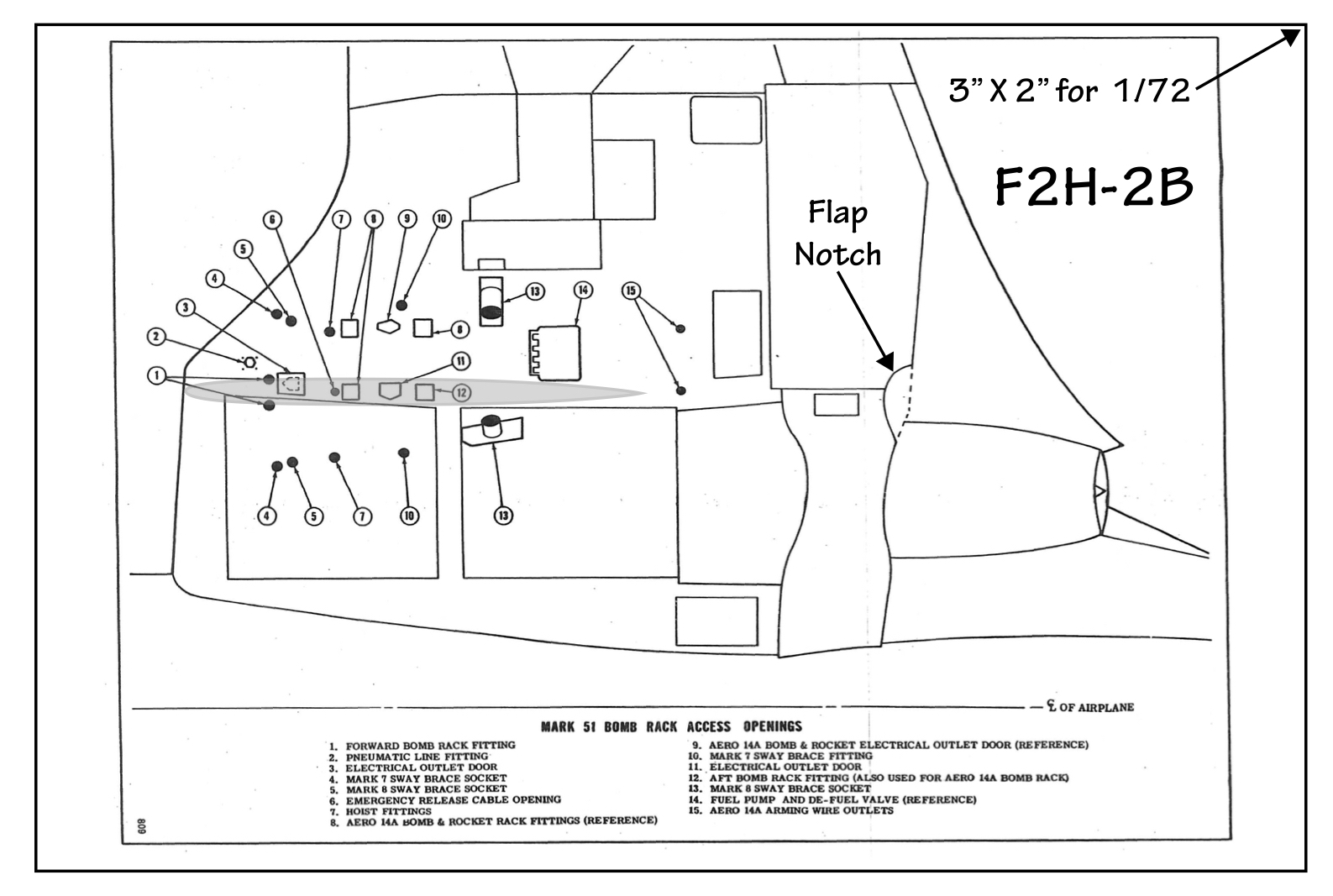
The pylon location, on the same wing station as the original inboard stores pylon, was the same for both bombs; a notch in the center section flaps was provided for Mk 7 clearance (not shown is the recess on the outboard center section flap for the Mk 8 fin clearance noted above).
 

 It was essentially coincident with the outboard edge of the engine intake opening:


Note that this initial capability predated the development of the Low Altitude Bomb System (LABS) delivery (click HERE). Instead, the bomb was to be dropped from altitude, in this example in a dive utilizing a "loft" bomb deliver capability, not to be confused with the loft options provided by LABS,

The flight manual advised caution not to exceed G limits when the Mk 7 was released in the loft maneuver; use of loft delivery for the much heavier Mk 8 was prohibited.

A couple of details on the Mk 7 development: 

Problems with its stability and trajectory were discovered during initial test drops. This was solved in part by adding wedges one one side of the tips of the tail fins that resulted in the bomb spiraling like a football.

Another was the initial use of barometric pressure to provide an air-burst capability for more wide-spread devastation. However, as the Mk 7 neared the ground, it was going faster than the measurement of the air pressure could keep up with from a detonation accuracy standpoint. As a result, speed brakes were initially provided between the tail fins that opened up when the bomb was dropped (it probably also provide a few vital seconds for the pilot to get far enough away to avoid getting "hoist by his own petard").

The addition of radar sensing of the height above ground resulted in them being deleted from the Mk 7.

Note that the Mk 8 did not have speed brakes because its raison d'etre was destruction of well-protected submarine shelters, accomplished by not detonating until as far below ground as possible, which meant that the faster it was going when it hit the ground, the better.

 The development of bespoke pylons (to be described in a subsequent post covering the F2H-3/4 nuclear-strike configuration) and more options for changing the angle of the tail cone allowed the Mk 7 to be loaded with the fins pointed upwards and eliminated the separate sway braces required for the Mks 7 and 8.

An important feature of the F2H-2B was the addition of the newly developed inflight refueling capability. This was accomplished by adding a fuel probe replacing one of the 20mm cannons on the right side of the fuselage.

Only the fuselage fuel tanks could be refilled in flight, probably because these early jets did not have single-point refueling capability. Also filling the tip tanks would have required the addition of additional fuel lines and flow management valves and controls. That was a tradeoff against the extra range that would be achieved, particularly since even though the store was mounted fairly close to the center line, the tip tank on that side could only be partially filled before takeoff since only so much lateral imbalance could be offset by the roll-control power (i.e. aileron effectiveness) available at low speeds. At cruise speeds, however, the imbalance could probably be accommodated, albeit at some increase in drag due to the control-surface deflection.

The early refueling probe had a tip that resembled a baby bottle nipple. It was subsequently replaced by the one that's now standard across U.S. and NATO probes.

There is currently a discrepancy in the number of F2H-2Bs. In my earlier post on Nuclear Banshees (see link above including comments) there were 25 to as many as 31, depending on the source. The effectivity given in the 15 January 1954 document provided by Mark Nankivil lists 60!:
125030-70
125500-05
125650-62

In any event, the F2H-2Bs were deployed in both "composite" squadron detachments and fighter squadrons:

This squadron's markings in color and regrettably, a bit out of focus:

The management of the store (arming, etc) was provided by a panel mounted on the right side of the cockpit above the console. Which panel was used depended on whether a Mk 7 or Mk 8 being carried.

Mk 7

Mk 8

Sunday, January 15, 2023

Roden 1/72 AJ-1 Savage Review


Model and Photo by Paul Boyer

Paul Boyer's review of the excellent Roden 1/72 scale AJ-1 kit here: Fine Scale Modeler

He mentions the windshield wiper location (note that this AJ-1 canopy has been modified with the larger escape hatch);


A couple of other easily fixable nits:

1. The AJ-1 had a single, rectangular (except for forward lower/right corner) nose landing gear door; the kit provides the AJ-2's two-piece door. An easy change:


2. The kit canopy represents the fix to the original sliding canopy with white fiberglass straps glued on it to strengthen it; only a few early production AJs were delivered with the version (I've not seen a picture of a Savage on a carrier with this canopy):

This was quickly replaced by a non-sliding, framed canopy:

In building the kit for review, Paul chose to simply paint the existing frames blue. However, a close approximation of the early AJ-1 canopy (note that it has a small sliding window beside both the pilot and bombardier) can be easily created by 1) sanding off the last transverse frame and the longitudinal frames fore and aft of it and 2) representing the structure on the back of the canopy with a thin layer of filler.

For more on the AJ Savage canopy variations, click HERE.

I was particularly impressed by the detail and accuracy of cockpit detail. Whoever did the research should be commended. The only minor exceptions, like some of the detail provided, will not be visible when the kit is assembled.

Kit parts 2K and 37K should provide for an opening under the flight deck to the left of the nose wheel well for access to the electronics forward (this is a photo of the AJ-2 at the National Museum of Naval Aviation):

The area aft of kit part 17E, which is the forward end of the fuselage fuel tank, should therefore be filled in to represent it accurately.

Note that there is a door/hatch in kit part 23K that was required when the nuke in the bomb bay had to be armed after takeoff. It may not be as tall as it should be since this installation shows it extending up to what is the bottom of the fuselage fuel tank...

I'm not sure that there should be an opening in kit part 15K but it's possible because 1) the jet engine firewall is aft of that and 2) the tanker installation requires a "fuel splash door" to be fitted here.

For other posts for reference for added detail, click HERE.


Saturday, December 24, 2022

Sikorsky RH-3A Sea King Minesweeper

 For a brief history of USN helicopter mine sweeping, click here: http://tailspintopics.blogspot.com/2022/12/a-brief-history-of-usn-helicopter.html

The RH-3A was the first of the Navy's mine-sweeping helicopters to be used operationally. Nine were converted from early production HSS-2 Sea Kings, BuNos 147139-142, 147144, 147146, 148038, and 148040-041. Some sources claim that conversions included 147138, but according to Tom Chee, it was stricken on 1 October 1959 as a result of Sikorsky flight-test related incident on 9 September 1959. RH-3A conversions didn't begin until December 1965.

The major changes to the SH-3A were the removal of all the ASW equipment and the addition of a large sliding door on the left side, bulged observation windows at the rear of the cabin on each side*, and rear-view mirrors for the pilot and copilot; a beef up of the lower aft fuselage above the tail wheel; and the addition of the mine-sweeping hardware including a tow reel in the cabin. They reportedly received a larger diameter, beefed-up tail rotor at some point due to the loads on the tail rotor while sweeping.

A right side view:

A left-side view:

Mine sweeping gear was deployed out of the right side of the cabin after attachment to the boom.

The mechanism required to rotate the boom and tow cable from alongside the cabin into the streaming position was pretty complicated:

Some other pictures:

The forward fuselage of an HC-7 RH-3A:

 An explanation of the "kill" scorecard by the forward entrance steps:

Jodie Peeler noted that RH-3As were also operated from Ozark (MCS-2):

Like Catskill (MCS-1), Ozark was a former minelayer/landing ship that was converted into an
oddball "mine warfare command and support ship," typical of the odd ducks often seen in this era of the Navy. A friend's dad served on Ozark in 1969 in that era (has recollections of being prepared for duty as
Atlantic Fleet recovery ship if Apollo 10 had gone wrong) and that's how I first became aware of the RH-3A.


What look like lifeboats are small mine-sweeping launches (MSLs). 

After being replaced by the RH-53A, the surviving RH-3As were stripped of the mine-sweeping hardware (but retained the cabin doors on each side and the bulged aft cabin windows) and redesignated UH-3As:

via Jodie Peeler

* Note that the combat-rescue HH-3As also had aft cabin windows on both sides but these were located one frame forward of the RH-3A's. HH-3As also did not have the left-side cabin sliding door.

Friday, December 23, 2022

A Brief History of USN Helicopter Minesweeping

Many of the problems that the helicopter was the solution for were identified in the decade or so after Larry Bell and Igor Sikorsky were successful with theirs. One was mine sweeping. In October 1950, the U.S. Navy needed to sweep the waters off Wonsan, Korea for an amphibious assault. Due to budget restrictions and the lack of need following World War II, mine-sweeping capability/capacity had been neglected by the U. S. Navy while other countries had focused on anti-ship mine development. As a result, a very small force of mine sweepers was tasked with clearing what proved to be an enormous field of Soviet-supplied mines. Light observation helicopters were used to spot mines ahead of the sweepers but the pilots and observers could only detect ones floating near the surface, a small portion of the defense-in-depth of various mine types. Although eventually successful in clearing an approach into the harbor, three mine sweepers were sunk, two USN and one ROK, and more than a dozen sailors killed.

The problem was that the mine sweeper on point, leading a wedge of mine sweepers clearing a channel, was too susceptible to being sunk by a mine. What a helicopter could do was tow sweeping gear ahead of the lead ship to minimize the risk to it of a mine encounter without risk to itself.

VX-1 commenced helicopter-tow testing with the Piasecki HRP-1 tandem-rotor helicopter in November 1952. It was the biggest, most powerful helicopter available at the time. For the testing off Panama City, Florida, they were stripped of fabric to reduce download and weight. Flotation was also added to allow for a water landing in the event of failure of its single engine.


The Navy borrowed at least one Piasecki H-21 helicopter from the Air Force in 1953 to evaluate it as a candidate for operational mine sweeping. The tandem-rotor configuration was preferred because all of the engine power went to lift and unlike a single-rotor helicopter with a tail rotor, it was insensitive to cross and tail winds.


In 1954, the Bureau of Aeronautics contracted with Bell Helicopter to make modifications to its HSL antisubmarine warfare helicopter to optimize it for mine sweeping. One requirement was to insure adequate engine cooling and oil supply at extreme nose-down attitudes.

By 1956, the HSL was successfully qualified as a mine sweeper and adequate numbers had been built for a mine-sweeping fleet. Here it is pulling a large salvage barge to demonstrate its towing capability.

However, when further HSL production for the ASW mission was cancelled in favor of the Sikorsky HSS-1 Sea Bat, the HSL was not deployed and utilized only for development of mine-sweeping gear. (For more on the Bell HSL program, see my monograph: http://tommythomason.com/books/Bell-HSL/)

In October 1962, the CNO directed BuAer to develop an operational helicopter minesweeper. The tandem-rotor Vertol H-46 was preferred but the decision was to convert nine early production SH-3As to the RH-3A configuration instead (the R prefix indicated a modification for reconnaissance, which apparently was considered to be the most descriptive of those available). Beginning in 1964, Sikorsky removed the ASW mission equipment from these helicopters and installed tow hardware on a beefed-up lower rear fuselage. A sliding door was added to the left side of the fuselage and a bulged observation window added on each side of the fuselage at the rear of the cabin.

In September 1966, NATC (Naval Air Test Center) accomplished a two-day shipboard suitability test of the RH-3A aboard Ozark (MCS-2). In 1967, HC-6 on the east coast and HC-7 on the west coast commenced operations with RH-3As.

Although demonstrating capability, there were teething-problems (the tail rotor proved inadequate and was reportedly replaced by a larger one, for example) and the RH-3A was under powered for some towing equipment. As a result, the Navy transferred 15 CH-53As from the USMC to AMCM (Airborne Mine Countermeasure) duty. These were equipped with more powerful engines and modified for the mine-sweeping mission. In addition to being larger and more capable, they had a rear ramp that made deployment, observation, and retrieval of the mine-sweeping gear much more straightforward. These were designated RH-53As and in 1971 assigned to a new helicopter squadron, HM-12, that was dedicated to mine sweeping.

In the meantime, BuAer had contracted with Sikorsky for 30 RH-53Ds, a derivative of the CH-53D Sea Stallion, which had first flown in January 1969. HM-12 received the first of these in August 1973. These were further refined for the mission, including the addition of inflight refueling capability.


Further development of the H-53 resulted in the CH-53E Super Stallion, a major upgrade that added a third T64 engine aft of the main transmission for even more power. The MH-53E Sea Dragon was the mine-sweeping variant, with the prefix "M" for multi-mission replacing the prior "R".  It featured huge sponsons for additional fuel capacity and a flight control system optimized for the mine-sweeping mission. The prototype first flew in December 1981. It was deployable in 1986, replacing the RH-53Ds. Fifty were built.

U.S. Navy photo by Chief Mass Communication Specialist Edward G. Martens

In the late 1990s, the CNO initiated a program for a set of AMCM systems to be utilized by deployed helicopter squadrons flying the MH-60S Knighthawk, which is otherwise utilized for cargo/personnel transport. It is not a mine sweeper per se, but can be equipped to spot some mine types and neutralize them. An MH-60S (HSC-28) and an MH-53E (HM-14) at NAS Key West during joint MCM exercises in 2021:

LT Rich Babauta

Friday, October 28, 2022

Hasegawa 1/72 CMV-22B Osprey

30 October: Added VRM-30 information

I am very pleased that Hasegawa elected to reissue their excellent 1/72 V-22 Osprey kit as the Navy's CMV-22B COD. For background on this aircraft and mission, see:

https://thanlont.blogspot.com/2011/05/carrier-onboard-delivery.html 

http://thanlont.blogspot.com/2013/02/cod-redux.html

I had bought the J.G.S.D.F Transport Aviation Group kit because it had some of the same antenna details and was contemplating how to add the greatly enlarged forward end of the sponsons (a CMV-22 unique feature that added extra fuel). Now that problem is solved and as an added bonus, I don't have to come up with the necessary decals.

Scott Van Aken provided a inbox review of the kit for Modeling Madness: https://modelingmadness.com/scott/21st/previews/has/02410.htm

One build note concerns the modification of the forward end of the sponson. Hasegawa provides a resin part that fits over the kit sponson to create the bulged one. It doesn't fit particularly well (nothing that trimming, filling, reshaping, sanding, etc. can't rectify) but beware, it doesn't fit particularly well three different ways, two of which are wrong. Worse, neither the sprue that they are on nor the parts themselves are marked to denote which side they go on. In Hasagawa's defense, the assembly illustrations do depict, if you examine them and the part closely, the correct orientation of the parts and which side they go on. However, the first time I dry fitted one, having just glanced at the instructions (Cavin: "Do I look like a sissy?"), I put it on incorrectly and was about to write that Hasegawa had got it wrong.

This is a bottom view of the sponsons:

This is the correct way to orient the part (note that the one in the picture taken from above is too far forward):

This is incorrect:

This is also incorrect:

Note that the upper surface of the addition at the same height as the original sponson; the bottom of it is flat (both laterally and longitudinally, see picture above) but lower than the belly (and the kit part may not go low enough).

The shape is very complex, particularly the forward outboard corner, which appears to be slanted outward from top to bottom:

There also appears to be an intersection where the forward end of the addition ends just before the forward end of the original sponson.

Note the straight line of the top of the sponson going forward, the symmetrical fore and aft bulge downward of the addition, and what appears to be a flat area at the forward outboard corner of the addition as noted above:


One oddity of the CMV-22B deployments so far is that none of the Ospreys have been marked with a unit tail code. That is, until now, assuming that "SB" has now been assigned to VRM-50.

And another, a crop of a photo by "manyinterests2020" on Reddit, tail code DC?

No unit marking on this aircraft, but the other CMV-22 COD unit is VRM-30 and the fin decoration is similar to its badge:

Many photos, pre fin color, here: https://www.seaforces.org/usnair/VRM/VRM-30.htm


Wednesday, August 31, 2022

Obscureco 1/72 F7U-3/3M Detail Set

 Obscureco Aircraft (http://www.obscureco.com/) has produced yet another detail set that will be of interest to U.S. Navy airplane modelers, OBS72030. It includes a full cockpit including an early and late ejection seat pan; the top of the fuselage behind the ejection seat including the canopy actuator; the nose gear wheel well; and a refueling probe. It replaces the equivalent "okay" parts provided in the otherwise excellent Fujimi F7U-3 kits with much more accurate and detailed resin ones.

The two-page instructions provide a detailed, step-by-step assembly guide and detailed color information.

Chris Bucholtz

Obscureco is in the process of updating their website so this kit may not yet be listed but it is available to order. The price is $20 plus the shipping cost provided here along with other purchasing information: http://www.obscureco.com/purchasing.html

Wednesday, August 3, 2022

Roden 1/72 North American AJ-1 Savage

13 November 2022: Illustrations of the inflight refueling system are provided here: http://tailhooktopics.blogspot.com/2022/11/north-american-aj-savage-carrier-based.html

 23 October 2022: Illustrations of the hardware required to fold the wings and vertical fin of the AJ are provided here: http://tailhooktopics.blogspot.com/2022/10/aj-savage-wing-and-fin-fold.html

22 October 2022: The kit out-of-the-box does not provide for open bomb bay doors. Many modelers would have no trouble separating the doors and assembling them in the open position. The configuration is illustrated here: http://tailhooktopics.blogspot.com/2022/10/aj-savage-bomb-bay-doors.html

4 August 2022: I've added a post summarizing the configuration of the different AJ Savage canopies here (at this point, the kit has the No 1 canopy that was on a few early AJ-1s):

http://tailhooktopics.blogspot.com/2022/08/north-american-aj-savage-canopies.html

3 August 2022: Totally unexpected:


I got a preview of the instructions and pictures of some of the tooling a month ago. It looks very good: lots of interior detail (and a Mk 4 bomb, around which the Savage was designed). One nit of confusion with the -2 configuration, easily remedied, is the nose landing gear door configuration (I had previously alluded to another one but incorrectly, as it turned out). While you're waiting, here is some reference material to peruse:

 https://tailspintopics.blogspot.com/2021/03/north-american-aj-savage-model-kits.html

https://tailspintopics.blogspot.com/2011/07/aj-savage-notes.html

https://tailspintopics.blogspot.com/2013/04/aj-2-savage-cockpit.html

https://tailspintopics.blogspot.com/2011/07/getting-it-right.html 

https://tailhooktopics.blogspot.com/2013/01/aj-savage-bombardier-station.html

More later...