I'm now pretty sure what the F-111B inflight refueling probe installation looked like, both originally and as planned for the production aircraft.
Thanks to Ray Geminski, we now have a photo of the short-nose probe extended:
My guess is that this is #5, BuNo 151974. One of the test points for #4, BuNo 151973, the day in crashed at Grumman was an evaluation of inflight refueling so it also had a probe.
The probe for the original short-nose design was located just aft of the bulkhead that the radar was mounted on. It swung up from the left side of the nose.
And then swiveled forward into position like the A-6 Intruder's.
In this picture, you can see what look like two of the three doors associated with the probe. My guess is that the lower door was hinged on its forward edge. The middle door was attached to the probe (see the picture above). The upper door was hinged on its right side and covered the opening at the base of the probe.
Although the probe was not installed on the first two or three flight test aircraft, it was on the fourth for certain because an inflight refueling evaluation was planned on what would be its last flight. I believe the picture of the unpainted F-111B and the one with the probe extended are both #5.
The extension of the nose for production allowing a more straightforward installation. The probe was now stowed on top of the nose under two doors and rotated up into position without having to swivel.
However, it doesn't appear that either of the two flight-test aircraft with the production nose had this installation. This was probably because the contour of the upper nose was different between the radome and the escape capsule on these airplanes. They were fitted with the original escape capsule whereas the production airplanes were to have a lower interface between the windscreen and the upper nose for better over-the-nose visibility. (See http://thanlont.blogspot.com/2009/03/f-111b-carrier-trials.html) In any event, the airplane had more than enough internal fuel for the typical flight-test mission so inflight refueling was not required.
by Tommy H. Thomason
Tuesday, January 17, 2012
Saturday, January 7, 2012
Corogard
Corogard*—also spelled Corrogard, Coroguard, Coro-gard, etc—was required by the Navy on the forward facing edges of inlets, wings, and empennages of some airplanes beginning in the mid 1950s. It was a clear epoxy paint that provided an additional degree of erosion and corrosion protection to those surfaces. However, the Navy specified that it be "aluminized" by the addition of aluminum power.
It's not clear when this requirement was first implemented. Don Fogal found a reference to the requirement in Squadron/Signal, Navy Air Colors, Vol. 2, 1945-1985, which cited specification MIL-C-18263(Aer) dated 23 February 1955 that revised paint and markings, including the introduction of the new gray/white paint scheme.
"The leading edges of airfoils and frontal surfaces were to be painted in an approved rain-erosion resistant finish. At this time the approved finishes for metal surfaces were an aluminized color and those approved for glass fiber reinforced plastic assemblies varied from Natural Tan to Black. The erosion-resistant finish was to be applied in such a manner that it would extend from the first row of rivets or fasteners on the upper surface to the first row of rivets or fasteners on the lower surface."
The use of Corogard or a clear erosion-resistant coating on the leading edge of the wings and empennage of jets predates this document and was not necessarily limited to the first row of rivets. However, the width of the erosion-resistant application was almost certainly controlled by a paint and marking for each airplane type and therefore always the same. For example, this is the Vought drawing that defines it for the F8U wing.
Note that the Navy repair and overhaul facility finish instructions might differ.
The leading edges of Navy jets were originally painted with the overall color.
However, high speed flight tended to remove the paint from the leading edges of the wings and empennage. The original fix appears to have been to leave these surfaces unpainted as on this early F9F Panther.
Also see http://tailspintopics.blogspot.com/2012/01/f9f-3-panther.html
Note that the amount unpainted surface on the Panther was subsequently increased.
There was likely some sort of corrosion protection provided on the leading edges, possibly a clear coat or post flight oiling. In any event, the use of the Corogard to protect the leading edges soon became standard. The practice was reportedly initiated at Grumman although I haven't been able to confirm that.
This is an example of the requirement for leading edge protection on the McDonnell F-4 (F4H) at a Navy Repair and Overhaul Facility:
This is a picture of the Sageburner F4H at the Smithsonian's Silver Hill storage facility. I'm not sure how soon the inlet was covered after the airplane was placed in storage by the Navy.
Since it was a relatively thick coat of clear epoxy mixed with aluminum powder, the perceived color and shininess varied with lighting and length of time since it had been applied. Some knowledgeable observers report it as being close to silver when new but that it weathered to a light gray. Another reported shade is close to aluminum lacquer paint. Another description is “semi-gloss medium metallic gray.”
Note the difference in the following two pictures between the leading edges of the wings and vertical fins.
It gets even more difficult to see in gray-scale pictures:
Unless the application is fresh and the lighting is right:
*3M filed for the wordmark "Corogard" in October 1951 and it was registered a year later. It is described as a "transparent protective coating material applied in liquid form ... said protective coating material drying after application to form a hard, tough transparent film." 3M allowed the trademark to expire in 1993.
It's not clear when this requirement was first implemented. Don Fogal found a reference to the requirement in Squadron/Signal, Navy Air Colors, Vol. 2, 1945-1985, which cited specification MIL-C-18263(Aer) dated 23 February 1955 that revised paint and markings, including the introduction of the new gray/white paint scheme.
"The leading edges of airfoils and frontal surfaces were to be painted in an approved rain-erosion resistant finish. At this time the approved finishes for metal surfaces were an aluminized color and those approved for glass fiber reinforced plastic assemblies varied from Natural Tan to Black. The erosion-resistant finish was to be applied in such a manner that it would extend from the first row of rivets or fasteners on the upper surface to the first row of rivets or fasteners on the lower surface."
The use of Corogard or a clear erosion-resistant coating on the leading edge of the wings and empennage of jets predates this document and was not necessarily limited to the first row of rivets. However, the width of the erosion-resistant application was almost certainly controlled by a paint and marking for each airplane type and therefore always the same. For example, this is the Vought drawing that defines it for the F8U wing.
Note that the Navy repair and overhaul facility finish instructions might differ.
The leading edges of Navy jets were originally painted with the overall color.
However, high speed flight tended to remove the paint from the leading edges of the wings and empennage. The original fix appears to have been to leave these surfaces unpainted as on this early F9F Panther.
Also see http://tailspintopics.blogspot.com/2012/01/f9f-3-panther.html
Note that the amount unpainted surface on the Panther was subsequently increased.
There was likely some sort of corrosion protection provided on the leading edges, possibly a clear coat or post flight oiling. In any event, the use of the Corogard to protect the leading edges soon became standard. The practice was reportedly initiated at Grumman although I haven't been able to confirm that.
This is an example of the requirement for leading edge protection on the McDonnell F-4 (F4H) at a Navy Repair and Overhaul Facility:
This is a picture of the Sageburner F4H at the Smithsonian's Silver Hill storage facility. I'm not sure how soon the inlet was covered after the airplane was placed in storage by the Navy.
Since it was a relatively thick coat of clear epoxy mixed with aluminum powder, the perceived color and shininess varied with lighting and length of time since it had been applied. Some knowledgeable observers report it as being close to silver when new but that it weathered to a light gray. Another reported shade is close to aluminum lacquer paint. Another description is “semi-gloss medium metallic gray.”
Note the difference in the following two pictures between the leading edges of the wings and vertical fins.
It gets even more difficult to see in gray-scale pictures:
Unless the application is fresh and the lighting is right:
There are very complicated ways to replicate it, but I tend toward just spraying on matte silver.
It appears that at some point the Navy stopped using Corogard and left the leading edges natural metal, for example on the F-14. A subsequent change in the early 1970s was to use a clear polyurethane self-adhesive tape developed by 3M on the leading edges, possibly only subsonic jets like the S-3 and A-6 initially. The tape would turn yellow over time from ultraviolet (UV) light exposure.
*3M filed for the wordmark "Corogard" in October 1951 and it was registered a year later. It is described as a "transparent protective coating material applied in liquid form ... said protective coating material drying after application to form a hard, tough transparent film." 3M allowed the trademark to expire in 1993.
Tuesday, January 3, 2012
Not a Jeep
David Collier provided me with a correction to a caption in Air Superiority. On page 49, there was a picture of an early F6U with an NC-1. I had written "The yellow low-slung jeep-like cart carries the array of batteries need to start these early jets." It turns out that this was the replacement for the jeep that lugged eight batteries around the deck and it didn't provide electrical power from batteries.
The new three-wheel NC-1 was equipped with a gasoline-powered generator to provide 24-volt current and also alternating current. It supplemented the fixed power stations at the catapults so the jets could be started elsewhere. The new starter jeep was modified from a standard jeep by O.E. Szekely & Associates of Philadelphia. The two wheels in the front were turned by the engine (i.e. front wheel drive) and did not turn for steering. The steering wheel (now mounted straight up and down) was connected to a third wheel under the back of the cart, allowing it to be turned in its own length. Deliveries began in late 1949 or early 1950.
The configuration changed over time. The one above may be an NC-1A, the suffix possibly added with the wedge in the hood covering an engine modification. The one wheel in back was apparently replaced by two and "training wheels" or "roll bars" were added at the rear corners to eliminate tip-over incidents. David provided the picture above as well as the following to illustrate the different configurations.
No anti-tip provisions, no wedge on the hood.
Wedge on the hood, training wheels:
No wedge on the hood, skids on the rear corners:
The NC-1/1A can be created from a jeep kit with some work. Alexsandr Survorov aka Phantom wrote about it here: http://www.dishmodels.ru/gshow.htm?p=5835&lng=E
This is a picture from that article of his conversion of an 1/72nd scale Hasegawa kit:
The NC-1A was replaced in the 1960s by larger, low-slung vehicles with turboshaft jet engines turning the generators. They could also be employed to tow aircraft. For more on flight deck tractors and start carts over the years, see http://www.carrierbuilders.net/forum/index.php?showtopic=1176
For more on the later tow tractors and power supply vehicles, see http://robdebie.home.xs4all.nl/models/mule.htm
The new three-wheel NC-1 was equipped with a gasoline-powered generator to provide 24-volt current and also alternating current. It supplemented the fixed power stations at the catapults so the jets could be started elsewhere. The new starter jeep was modified from a standard jeep by O.E. Szekely & Associates of Philadelphia. The two wheels in the front were turned by the engine (i.e. front wheel drive) and did not turn for steering. The steering wheel (now mounted straight up and down) was connected to a third wheel under the back of the cart, allowing it to be turned in its own length. Deliveries began in late 1949 or early 1950.
The configuration changed over time. The one above may be an NC-1A, the suffix possibly added with the wedge in the hood covering an engine modification. The one wheel in back was apparently replaced by two and "training wheels" or "roll bars" were added at the rear corners to eliminate tip-over incidents. David provided the picture above as well as the following to illustrate the different configurations.
No anti-tip provisions, no wedge on the hood.
Wedge on the hood, training wheels:
The NC-1/1A can be created from a jeep kit with some work. Alexsandr Survorov aka Phantom wrote about it here: http://www.dishmodels.ru/gshow.htm?p=5835&lng=E
This is a picture from that article of his conversion of an 1/72nd scale Hasegawa kit:
The NC-1A was replaced in the 1960s by larger, low-slung vehicles with turboshaft jet engines turning the generators. They could also be employed to tow aircraft. For more on flight deck tractors and start carts over the years, see http://www.carrierbuilders.net/forum/index.php?showtopic=1176
For more on the later tow tractors and power supply vehicles, see http://robdebie.home.xs4all.nl/models/mule.htm
Friday, December 23, 2011
Where's His Parachute?
In the typical picture of an Air Force pilot on the ramp going to and from his airplane, he is wearing a parachute. Navy pilots, rarely after flight school. At some point before mid-July 1944, probably much earlier, parachutes were left in the cockpits of carrier-based airplanes, doubtless to avoid any possibility of a parachute opening accidentally on the flight deck. From the 1 July 1944 issue of Naval Aviation News, page 33:
In order to make strapping in less of a hassle, the pilot was provided with a parachute harness to wear to and from the airplane. It had two straps hanging down from the shoulders with clips at the bottom to attach to the parachute pack in the seat pan.
The crotch straps dangling down from the bottom of the harness were often left unattached for comfort while walking to and from the airplane.
This separate harness seems to have disappeared after the war but the parachutes (usually back packs) still remained in the cockpit as evidenced by this Marine FJ-2 pilot saddling up.
The torso harness was reinvented by Douglas for use with the A4D ejection seats. Astronaut Alan Bean has a picture of him in one on his website, http://www.alanbean.com/naval_aviator.cfm
(He's also wearing an anti-blackout or g-suit.)
The torso harness became standard at some point with the Martin-Baker ejection seats.
For much, much more on flight suit gear, see: http://heritageflightgeardisplays.wordpress.com/
In order to make strapping in less of a hassle, the pilot was provided with a parachute harness to wear to and from the airplane. It had two straps hanging down from the shoulders with clips at the bottom to attach to the parachute pack in the seat pan.
The crotch straps dangling down from the bottom of the harness were often left unattached for comfort while walking to and from the airplane.
This separate harness seems to have disappeared after the war but the parachutes (usually back packs) still remained in the cockpit as evidenced by this Marine FJ-2 pilot saddling up.
The torso harness was reinvented by Douglas for use with the A4D ejection seats. Astronaut Alan Bean has a picture of him in one on his website, http://www.alanbean.com/naval_aviator.cfm
(He's also wearing an anti-blackout or g-suit.)
The torso harness became standard at some point with the Martin-Baker ejection seats.
For much, much more on flight suit gear, see: http://heritageflightgeardisplays.wordpress.com/
Wednesday, November 16, 2011
Lockheed P-80A Carrier Trials
As a result of a Jared Zichek Navy P-80A post in Retro Mechanix (see http://retromechanix.com/ for his web site), I took a trip in the way-back machine to a Tailhook Topics column in an IPMS Update:
Jared posted some terrific pictures that he found at the National Archives providing details of the modifications involved. See http://retromechanix.com/lockheed-p-80a-for-the-u-s-navy-1945/ (I don't know how he keeps coming up with some of this stuff; I've been there many times and never seen this particular report.)
The pictures solve a mystery for me. It turns out that the tailhook was installed in a recess on the bottom of the fuselage. One unusual aspect of the installation is that the pivot point for the tailhook was on the aft end of a bell crank that tilted down when the tailhook was lowered. As a result, when the hook is down, it appears to be externally mounted. The arrangement kept the hook from damaging the fuselage, since the bell crank lowered the front end of the hook so the aft end hit a transverse bumper on the bottom of the fuselage if it happened to bounce or be pulled that high. All that will make more sense when you look at the pictures that Jared has posted.
Another unusual aspect of the modification was that the airplane could be attached to the catapult shuttle with either a pendant, which attaches to only one point on the aircraft, or a bridle, which attaches to two points. The bridle arrangement was the most common up until then, mainly because the landing gear represented two strong points to attach a bridle to and stores on the centerline made it difficult to find a place to locate a pendant.
Both bridle and pendant configurations were evaluated for catapult launch of the Navy's P-80A. The bridle cable was attached to a hook on each wing and passed in front of the catapult shuttle.
The pendant was shorter and therefore lighter as well as easier for the deck crew to attach: one end was looped around the catapult shuttle and the other to an attach point on the bottom of the forward fuselage. However, there was some concern that the launch would be more exciting with the pendant if the airplane was lined up a bit crooked or offset relative to the catapult track.
In shore-based testing, the bridle was found to cause too much nose-up pitch at nominal accelerations and end speeds. At 2.6 g and 75 mph end speed, the tail pipe came within four inches of the deck.
The pendant did not cause a pitch up but was found to ding the aircraft on release; however, this was attributed to the shore-based catapult installation that had a track sunk below ground level. No problem was encountered with a non-perfect lineup.
In the shipboard trials aboard FDR on 1 November 1946, Marion Carl made four deck runs (starting from virtually the fantail) and two catapult launches at fairly light gross weights and about 35 knots wind over deck. All were satisfactory.
The drawing incorrectly depicts a tall thin mast in front of the windscreen (see http://tailspintopics.blogspot.com/2016/02/lockheed-p-80a-carrier-trials-mea-culpa.html). The side view drawing above is also incorrect with respect to the location of the forward end of the tailhook and its overall length. I had assumed that the tailhook would be attached forward of the fuselage break from a structural standpoint. The pictures on Jared's website referenced above provide a much better idea of the installation and show it to be attached aft of the fuselage break.
Rumor has it that the P-80 was ready for carrier trials before the McDonnell FH-1 Phantom was. According to one account, the P-80 team had to wait for the Navy's jet fighter to be first to operate from a U.S. carrier at sea. (As in many other things associated with aircraft carriers in those days, however, the Brits were the first to fly a jet to and from one.)
You'll note that the airplane does not have tip tanks. The Navy determined that the P-80's carrier suitability was marginal without them and unacceptable with them. See http://retromechanix.com/lockheed-p-80a-for-the-u-s-navy-1947/
Several minor modifications are required to accurately represent the P-80A. For one thing, it did not have an ejection seat. The windscreen was about nine inches farther aft than later P-80s and aft end of the canopy ended in a point, not a half-round "tail." The landing light was located in the tip of the nose rather than on the nose landing gear and the pitot, on the upper leading edge of the tail fin, not under the forward fuselage. A wire radio antenna ran from the canopy to the leading edge of the vertical fin.The red turbine warning stripe was not yet used. However, my guess is that it did have red lines around the flaps on the upper wing surface. My notes say that the airplane was AN512 light gloss gray, something very close to FS 16492 according to Dana Bell. Based on fuselage station drawings provided by Gerry Asher, this is my best guess at the windscreen location of the A and the B/C airplanes:
Also, when the windscreen was moved forward on the P-80B to provide clearance for an ejection, the sliding portion of the canopy was lengthened so that its aft end remained in the same place as on the A. Cutting the "tail" off the end of the F-80C canopy and sanding it to a point will approximate the P-80A canopy. For the correct length, you'll have to shorten the sliding canopy by cutting about six-seven inches off the front of it.
Note that the P-80A canopy had structure spanning the side rails aft of the cockpit opening and fittings at the lower front corners that lifted the forward end up as it slid aft. (The gunsight is not shown.)
This inboard profile of the P-80A forward fuselage shows the instrument panel located at the base of the windscreen, the cantilevered gun sight, and the bucket seat:
The location of the aft cockpit bulkhead, instrument panel, and flight controls were the same relative to the airframe as in the P-80B's and C's. The gun sight appears to have not been as cantilevered in the ejection-seat equipped P-80s, retaining the same relationship to the windscreen.
This is my conversion of the 1/72 Airfix P-80 kit:
I vacuformed a new canopy using the Airfix canopy modified to be a master.
The 1/72 new Sword P-80A/B kit provides both the bucket seat for the A as well as the ejection seat for the B, but unfortunately the windscreen location and sliding canopy are only provided for the B.
Gerry Asher provides 1/48 and 1/72 P-80A conversion kits as well as 1/48 details and decals for the Navy carrier-trials P-80. This is his build:
He also sells many other conversion kits and decals for the Lockheed P-80/T-33/F-94 series as well as other jets of that era. Contact him for a list of his kits at gmasher@netzero.net and also ask to be added to his email list.
Lockheed proposed production of a carrier-based P-80B but the Navy already had a plateful of jet fighters in work. In 1946 or 1947, the Navy obtained another P-80A and a P-80B from the Army for missile chase (and destroy, if necessary) at Point Mugu. See http://herschpahlbooks.com/dedications/cliff_weirick.htm.
In early 1948, the Navy realized that an expeditious transition to jet fighters required more airplanes sooner than Grumman and McDonnell could build them. The solution was to buy 50 P-80Cs from the Air Force to “train pilots and maintenance personnel in operation of jets.” These were stock 50 P-80s (49 P-80C-1-LO and 1 P-80C-5-LO), designated TO-1s since the Navy considered them to be trainers and they were not carrier capable. They were assigned BuNos 33821-33870. They were all originally based in the San Diego area, “to simplify problems of maintenance and logistic support”. VMF-311 received 12 and operated them from MCAS El Toro, California. VF-6A, to be redesignated VF-52, initially received 24. In effect, both squadrons functioned as the initial jet transition training units. The rest of the P-80Cs were held in reserve for attrition.
Note the pitot under the forward fuselage, dielectric panel on the nose, windscreen set farther forward on the fuselage, ejection seat, etc.
Jared posted some terrific pictures that he found at the National Archives providing details of the modifications involved. See http://retromechanix.com/lockheed-p-80a-for-the-u-s-navy-1945/ (I don't know how he keeps coming up with some of this stuff; I've been there many times and never seen this particular report.)
The pictures solve a mystery for me. It turns out that the tailhook was installed in a recess on the bottom of the fuselage. One unusual aspect of the installation is that the pivot point for the tailhook was on the aft end of a bell crank that tilted down when the tailhook was lowered. As a result, when the hook is down, it appears to be externally mounted. The arrangement kept the hook from damaging the fuselage, since the bell crank lowered the front end of the hook so the aft end hit a transverse bumper on the bottom of the fuselage if it happened to bounce or be pulled that high. All that will make more sense when you look at the pictures that Jared has posted.
Another unusual aspect of the modification was that the airplane could be attached to the catapult shuttle with either a pendant, which attaches to only one point on the aircraft, or a bridle, which attaches to two points. The bridle arrangement was the most common up until then, mainly because the landing gear represented two strong points to attach a bridle to and stores on the centerline made it difficult to find a place to locate a pendant.
Both bridle and pendant configurations were evaluated for catapult launch of the Navy's P-80A. The bridle cable was attached to a hook on each wing and passed in front of the catapult shuttle.
The pendant was shorter and therefore lighter as well as easier for the deck crew to attach: one end was looped around the catapult shuttle and the other to an attach point on the bottom of the forward fuselage. However, there was some concern that the launch would be more exciting with the pendant if the airplane was lined up a bit crooked or offset relative to the catapult track.
In shore-based testing, the bridle was found to cause too much nose-up pitch at nominal accelerations and end speeds. At 2.6 g and 75 mph end speed, the tail pipe came within four inches of the deck.
The pendant did not cause a pitch up but was found to ding the aircraft on release; however, this was attributed to the shore-based catapult installation that had a track sunk below ground level. No problem was encountered with a non-perfect lineup.
In the shipboard trials aboard FDR on 1 November 1946, Marion Carl made four deck runs (starting from virtually the fantail) and two catapult launches at fairly light gross weights and about 35 knots wind over deck. All were satisfactory.
The drawing incorrectly depicts a tall thin mast in front of the windscreen (see http://tailspintopics.blogspot.com/2016/02/lockheed-p-80a-carrier-trials-mea-culpa.html). The side view drawing above is also incorrect with respect to the location of the forward end of the tailhook and its overall length. I had assumed that the tailhook would be attached forward of the fuselage break from a structural standpoint. The pictures on Jared's website referenced above provide a much better idea of the installation and show it to be attached aft of the fuselage break.
Rumor has it that the P-80 was ready for carrier trials before the McDonnell FH-1 Phantom was. According to one account, the P-80 team had to wait for the Navy's jet fighter to be first to operate from a U.S. carrier at sea. (As in many other things associated with aircraft carriers in those days, however, the Brits were the first to fly a jet to and from one.)
You'll note that the airplane does not have tip tanks. The Navy determined that the P-80's carrier suitability was marginal without them and unacceptable with them. See http://retromechanix.com/lockheed-p-80a-for-the-u-s-navy-1947/
Several minor modifications are required to accurately represent the P-80A. For one thing, it did not have an ejection seat. The windscreen was about nine inches farther aft than later P-80s and aft end of the canopy ended in a point, not a half-round "tail." The landing light was located in the tip of the nose rather than on the nose landing gear and the pitot, on the upper leading edge of the tail fin, not under the forward fuselage. A wire radio antenna ran from the canopy to the leading edge of the vertical fin.The red turbine warning stripe was not yet used. However, my guess is that it did have red lines around the flaps on the upper wing surface. My notes say that the airplane was AN512 light gloss gray, something very close to FS 16492 according to Dana Bell. Based on fuselage station drawings provided by Gerry Asher, this is my best guess at the windscreen location of the A and the B/C airplanes:
Note that the P-80A canopy had structure spanning the side rails aft of the cockpit opening and fittings at the lower front corners that lifted the forward end up as it slid aft. (The gunsight is not shown.)
Created from illustrations provided by Gerry Asher
Photo by Gerry Asher of Navy P-80A BuNo 29689
The location of the aft cockpit bulkhead, instrument panel, and flight controls were the same relative to the airframe as in the P-80B's and C's. The gun sight appears to have not been as cantilevered in the ejection-seat equipped P-80s, retaining the same relationship to the windscreen.
This is my conversion of the 1/72 Airfix P-80 kit:
I vacuformed a new canopy using the Airfix canopy modified to be a master.
The 1/72 new Sword P-80A/B kit provides both the bucket seat for the A as well as the ejection seat for the B, but unfortunately the windscreen location and sliding canopy are only provided for the B.
Gerry Asher provides 1/48 and 1/72 P-80A conversion kits as well as 1/48 details and decals for the Navy carrier-trials P-80. This is his build:
He also sells many other conversion kits and decals for the Lockheed P-80/T-33/F-94 series as well as other jets of that era. Contact him for a list of his kits at gmasher@netzero.net and also ask to be added to his email list.
Lockheed proposed production of a carrier-based P-80B but the Navy already had a plateful of jet fighters in work. In 1946 or 1947, the Navy obtained another P-80A and a P-80B from the Army for missile chase (and destroy, if necessary) at Point Mugu. See http://herschpahlbooks.com/dedications/cliff_weirick.htm.
In early 1948, the Navy realized that an expeditious transition to jet fighters required more airplanes sooner than Grumman and McDonnell could build them. The solution was to buy 50 P-80Cs from the Air Force to “train pilots and maintenance personnel in operation of jets.” These were stock 50 P-80s (49 P-80C-1-LO and 1 P-80C-5-LO), designated TO-1s since the Navy considered them to be trainers and they were not carrier capable. They were assigned BuNos 33821-33870. They were all originally based in the San Diego area, “to simplify problems of maintenance and logistic support”. VMF-311 received 12 and operated them from MCAS El Toro, California. VF-6A, to be redesignated VF-52, initially received 24. In effect, both squadrons functioned as the initial jet transition training units. The rest of the P-80Cs were held in reserve for attrition.
Note the pitot under the forward fuselage, dielectric panel on the nose, windscreen set farther forward on the fuselage, ejection seat, etc.
Sunday, October 23, 2011
F3H Beaver Tails
I've updated the F3H entry with pictures and an illustration of the two different beaver tails and also a picture of the two 20 mm cannon modification: http://tailspintopics.blogspot.com/2010/11/f3h-demon.html
Wednesday, October 19, 2011
Yankee Tractor Rocket Escape System
The retrofit of the Air Force A-1 Skyraiders, both single seat and wide body, with the Stanley Aviation Corporation Yankee escape system is fairly well known. As it turns out, this was a Navy initiative and at least two squadrons had their aircraft modified with this capability, VA-25 (Coral Sea) and VA-152 (Oriskany). It is properly described as an extraction system as opposed to an ejection seat, since the seat stays in the aircraft and the pilot is pulled out by the rocket as opposed to being pushed out.
VA-25
VA-152
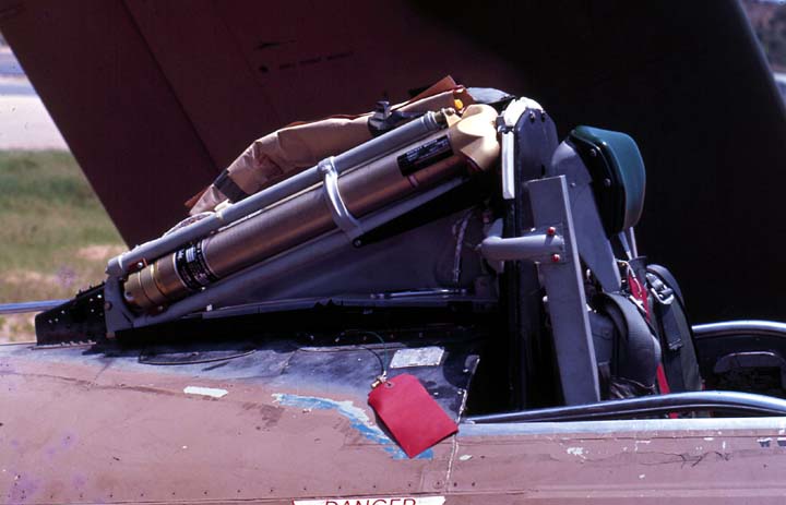
The retrofit was fairly simple. VA-25 reportedly had all 12 of its aircraft modified midcruise in a couple of weeks at NAS Cubi Pt, Philippine Islands in November 1967 while Coral Sea was off the line. It basically consisted of a rocket located under the canopy behind the pilot's head and a different seat/headrest. The rocket was connected to two ten-foot lines that were attached to the pilot's parachute harness.
The rocket was installed to the right of the existing canopy actuation mechanism.
(Note that this mechanism was usually covered by canvas before the Yankee seat was installed.)
When the pilot activated the system by pulling a D-ring located between his thighs, the canopy was jettisoned and the rocket tilted upward and fired, extracting the pilot out of the cockpit. This is a test using a civil-registered T-6G.
The system was rated for zero airspeed and zero altitude but only with zero sink rate and zero pitch/roll. A zoom climb was therefore recommended before jettisoning the airplane.
Although light weight, the extraction concept was most appropriate at the relatively low speeds usually attained by propeller driven aircraft although Stanley did sled tests at high subsonic speeds (see YouTube link below).
For more stuff on the Yankee seat, see:
http://skyraider.org/skyassn/otherpics/cole/Yankee.jpg
http://skyraider.org/hook/dashonet/yankee.htm
http://users.bestweb.net/~kcoyne/frame_sg.htm (Click on the Stanley "Yankee" button well down in the left column )
https://www.youtube.com/watch?v=8Yw8g1Soigk
For a comparison with the original seat, see http://tailspintopics.blogspot.com/2013/11/ad-1-skyraider-standard-vs-extraction.html
VA-25
VA-152
The retrofit was fairly simple. VA-25 reportedly had all 12 of its aircraft modified midcruise in a couple of weeks at NAS Cubi Pt, Philippine Islands in November 1967 while Coral Sea was off the line. It basically consisted of a rocket located under the canopy behind the pilot's head and a different seat/headrest. The rocket was connected to two ten-foot lines that were attached to the pilot's parachute harness.
The rocket was installed to the right of the existing canopy actuation mechanism.
(Note that this mechanism was usually covered by canvas before the Yankee seat was installed.)
When the pilot activated the system by pulling a D-ring located between his thighs, the canopy was jettisoned and the rocket tilted upward and fired, extracting the pilot out of the cockpit. This is a test using a civil-registered T-6G.
Although light weight, the extraction concept was most appropriate at the relatively low speeds usually attained by propeller driven aircraft although Stanley did sled tests at high subsonic speeds (see YouTube link below).
For more stuff on the Yankee seat, see:
http://skyraider.org/skyassn/otherpics/cole/Yankee.jpg
http://skyraider.org/hook/dashonet/yankee.htm
http://users.bestweb.net/~kcoyne/frame_sg.htm (Click on the Stanley "Yankee" button well down in the left column )
https://www.youtube.com/watch?v=8Yw8g1Soigk
For a comparison with the original seat, see http://tailspintopics.blogspot.com/2013/11/ad-1-skyraider-standard-vs-extraction.html
Subscribe to:
Posts (Atom)