12 November 2025: Corrected cannon case/link ejection location


Thanks to his research and the files of my F3D subject-matter expert, Paul Bless, I have reappeared out of this particular rabbit hole with information new to me if not to you.
First, text from the Erection and Maintenance Manual:


However, an opening in the aft end of the nose landing gear door is usually still present: this was where the cartridge cases and clips were dumped overboard (the corresponding ones for the outboard cannons were located farther forward and outboard of the nose gear compartment).


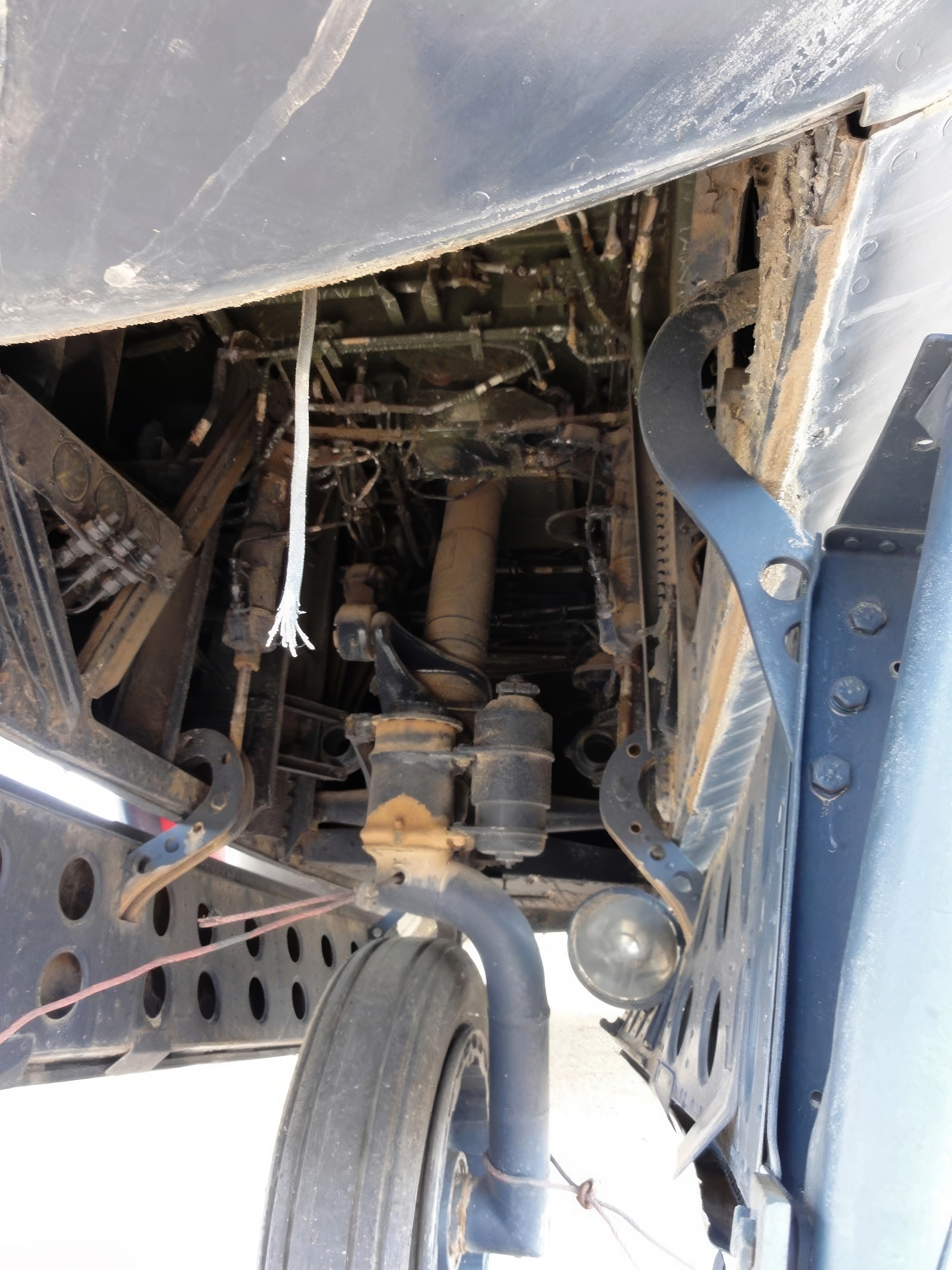
From Paul Bless Photo
The nose gear bay opening is not as wide as it appears from the front based on the location of the nose landing gear doors because they are mounted on goose-neck hinges.

But the opening is also much longer than it needs to be, apparently to provide for access to the ammunition feed to the cannons.

In an F3D nose wheel well I looked up into, roughly the aft half of the opening was closed off by a panel, but at the moment I don't know if that was original or something added when the Skyknight was prepared for display.


I first became aware of the F3D some 70 years ago when it was the first model I built by myself. Up until now, I believed that the escape chute for the crew somehow exited at the back of the nose gear well. Now it seems all that extra space aft of the strut was taken up by guns, aviation HVAC and such, leaving the hapless crew to depart a stricken airplane even farther aft than that, somewhere between the engines or thereabouts. It is a very good thing that the Flying Drut was a bit portly or it would have been a tight squeeze. Cheers to you, Tommy. You never cease to educate.
ReplyDeleteThanks for that.
ReplyDeleteI spotted the panel in the display aircraft and puzzled like you for a while. I think, however, that it's just a half hearted effort to minimize the wildlife taking up residence aboard. There just isn't room for the nosewheel to retract . Lets hope kit and aftermarket resin designers don't spot it.
Perhaps it's looking at all those head-on shots but I think I've spotted something else that's been overlooked in F3Ds: the radome shape. It's not circular in section at the rear and this might be why kit designers are not getting the windscreen lofting right. The could have it right in profile and have a circular section but this would leave the fairings having too much to do at the sides.
With respect to the nose landing gear, it retracts forward as shown in the first illustration and the last one. The pivot point is below the shock strut and therefore it rotates aft and still stays within the wheel well, allowing there to be a panel closing the well off from below (I don't know that there was one). However, you are correct that the fuselage cross section flattens at the top forward of the windscreen and the aft end of the radome is not a circle. There is one front view illustration in the F3D-2 Maintenance Instructions that depicts it that way as well as in some isometric drawings depicting the location of systems and components.
DeleteAs the last illustration shows, the retracted nosewheel and tire is the full depth of the bay - the roof of which is the cockpit floor. There just isn't any space left to close off above the tire.
DeletePerhaps the person in charge of this exhibit looked at the matchbox kit and realized the plane needed correcting!
Having looked at the photos and drawings accompanying this post for a minute, I’d say there is indeed a panel low in the well behind the nosewheel and, to me, it appears to be a factory item - it has that look. Its existence is also suggested by a line in the last drawing if you look for it. I would imagine it was there to protect the guns’ firing mechanisms from grit and FOD. It almost certainly would have been hinged or removable, otherwise there would be no way to remove or service the canon and other equipment in the gear bay.
ReplyDeleteI see what you mean now.
DeleteThat appears to be about half way between the centre and rear door hinges. That would put it somewhere around the gun breaches and the ejector chutes. Logically, it needs something around there to support the chutes and the guns themselves and it looks solidly built; structural rather than an enclosure. Above that are the guns and then the bottom of the escape slide in the middle and the ammo boxes either side.
Blast tubes remains:
ReplyDeletehttps://web.archive.org/web/20150818160127if_/http://www.philsaeronauticalstuff.com/f3d/images/f3dnosegear-4a.jpg
https://web.archive.org/web/20150818160127if_/http://www.philsaeronauticalstuff.com/f3d/images/f3dnosegear-6a.jpg
Escape hatch:
https://web.archive.org/web/20150818160127if_/http://www.philsaeronauticalstuff.com/f3d/images/f3dnosegear-5a.jpg