Sunday, January 29, 2017

F8U/F-8 Unit Horizontal Tails

Unit Horizontal Tail (UHT) was the Vought term-of-art for the all-moving stabilator. When the F8U-2NE (F-8E) was adapted for the French Navy requirement, the wing was modified with a two-segment leading-edge flap and boundary layer control for a reduction in approach speed.

A new, larger UHT was required as a result. When the U.S. Navy upgraded some of its F-8Es to the F-8J configuration, this wing and horizontal tail was used to accommodate the increase in gross weight.

Thanks to Tom (Superheat) Weinel and Vought data, I'm finally able to create a pretty good illustration showing not only a size comparison of the larger horizontal tail but where it was located on the fuselage relative to the original one.
There are reports that the change was accomplished simply by adding a leading edge cuff. I'm pretty sure that the cuff in question was incorporated to protect the leading edge from the blast of fuselage-mounted rockets and missiles, not to enlarge the UHT.

Although the UHT was mounted with dihedral of 5° 25', I was unable to determine if the spans given were actual (tip to tip when attached), or of the UHT without dihedral. My guess is that the span was with no dihedral, which is how I created the illustration above. In any event, the difference in span is only about 1/2 inch.

For a summary of F8U/F-8 differences, see http://tailspintopics.blogspot.com/2009/10/f8u-crusader-variations.html


Monday, January 23, 2017

The F-111B Auxiliary Flap

24 January 2017: Updated with additional information and a photo. Also see this earlier post on the Auxiliary Flap: http://tailspintopics.blogspot.com/2014/09/f-111-auxiliary-flaps.html

Steven Hyre recently posted some excellent exploded views of the F-111 wing on his Facebook page, The F-111 Historical Association. One of them reminded me that I was still hoping to find a picture of the F-111 auxiliary flap.
It was a small flap added inboard of the existing flaps in the narrow space between the most inboard of them and the fuselage. It was electrically actuated separately from the original hydraulically actuated flap system and could only be extended when the wing was swept fully forward. As shown on the drawing above, it was effective on "Navy 6" and above, which meant BuNo 152714 and subsequent F-111Bs.
Given its small size, it is apparent that Grumman was grasping at every opportunity to increase lift and reduce the nose-down attitude of the F-111B on approach.

The production F-111B flight manual describes it in some detail. Extension and retraction were automatic but subject to limitations, e.g. it would only extend if the wings were full forward and the wing flaps were extended 28 degrees or more.

However, I had never seen any photographic evidence of it. Here are a couple of closeups of the inboard section of the wing of "Navy 6" with the flaps down.


Now it's possible that the wing in the first picture above is not fully unswept but it would appear that it is in the picture below it (note how close the wing leading edge is to the lower door of the rotating glove installation). In any event, no auxiliary flap is apparent in either one.

Posting a request for information on the F-111 Historical Association Faeebook page quickly resulted in some. Steven Hyre noted that a USAF tech instruction was issued in October 1968 to deactivate the auxiliary flap on F-111As and Cs and FB-111s, which was very early on in the F-111 program, e.g. the first production FB-111 first flew on 13 June 1968 and the first F-111C flew in July 1968 (and promptly disappeared into long-term storage). The extension limits and early deactivation explain its rare appearance in photographs.

Kevin Morrison wrote that the auxiliary flap was disconnected because it was tearing up the lower fairing seal of the fuselage opening into which the wing trailing edge swept. Bill Lassiter remembers that the lift benefit was pretty limited and there was concern that the need to first retract the auxiliary flap might delay an urgent need to sweep the wings from full forward for whatever reason.

And best of all, Patrick Flohe provided the following closeup of the auxiliary flap lowered on an F-111A. Note that the upper surface is not skinned as shown on the F-111B illustration above.

He also noted that at the time the photo was taken, this airplane still had the original aft main landing gear door that opened parallel to the bottom of the fuselage.

Saturday, January 14, 2017

F2H Banshee Canopies

16 January 2017: Bill Gilman noted (see his comment below) that the later canopy seemed to be more bulged laterally. I had wondered about this in passing but hadn't taken a close look at it. However, it's obvious, certainly the shape of the frames between the windscreen and sliding canopy.
I'm not sure that the later sliding canopy is bulged more laterally very far aft of its bow. The color picture on the right was taken by Don Hinton of the F2H-2P at the National Naval Aviation Museum in Pensacola. A set of his pictures is available at Phil's Aeronautical Stuff here: http://www.philsaeronauticalstuff.com/f2h-2p/f2h-2p.html

There were two different F2H Banshee canopies, not counting the one on the original XF2D-1 prototypes.
It had a shorter sliding section and a somewhat different windscreen, particularly its forward interface with the fuselage. Note also that Bob Edholm is testing an XF2D without the benefit of an ejection seat.

For some reason, after completion of F2H-1 production and not quite half of the F2H-2s, McAir elected to produce the remainder, beginning with BuNo 124940, with a slightly different canopy. The center panel of the windscreen, which had been straight sided, was now an oval with heavier framing.
 (The red post in the color picture on the left is the Davis barrier activator; it was spring-loaded to extend when the tailhook was lowered. It was stowed manually after landing as shown in the gray-scale photo on the right.)

I only have a McAir lines drawing for the later canopy.

The sliding canopy bow, which had had a flattened top, now had a smooth curve.
It appears to me that the center panel of the new windscreen was raised slightly, parallel to the original one, as evidenced by the steeper slope of the fairing at its front edge. It's possible that the change was to provide better visibility of the LSO on the approach to the carrier.
I don't know how many F2H-2s produced prior to BuNo 124940 were retrofitted. I do have photographs of two, both F2H-2Ns, BuNos 123300 and 123301, with the later canopy.
Note the unpainted sheet metal of the fuselage-skin change required.

Wednesday, January 11, 2017

Markings - A Cautionary Tale Continued

For the first post on this topic, see http://tailspintopics.blogspot.com/2012/06/markings-cautionary-example.html

This example was provided by Joe Turpen:
Note the the marking of the side number and tail code markings on the right wings. Those on three of the F3H-2s appear to have been applied by the same person or at least in accordance with the same guidelines: size, location, orientation, etc. The width of the number varies because of the width of the individual digits, with 203 taking up more of the wing than 211.

However, the marking of the Demon on the bottom of the picture is notably different. The numbers are slanted and the tail code appears to be bolder.

A minor detail, certainly, but another example of variation when none is expected.

Tuesday, January 10, 2017

Corogard on the A4D (A-4)

Corogard was a protective treatment on the leading edges of U.S. Navy airplanes at one time. For background, see http://tailspintopics.blogspot.com/2012/01/corogard.html

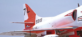
I was recently asked a question about its applicability to the A4D (A-4) Skyhawk. There's no question that it was initially part of the production paint scheme as shown on this early A4D-1.

It's pretty obvious on this reserve A4D-1. Note that the vertical fin application is narrow and doesn't appear to extend onto the dorsal fin.

However, this YA4D-1, circa 1956, doesn't appear to have any Corogard on any leading edges although the gull gray appears to have been wrapped around to the lower surface of the horizontal tail for a short distance (and probably to the aft edge of the bottom of the wing slat as well).

In some cases, the squadron trim color was applied to the leading edge of the vertical tail with no Corogard evident and even the wing leading edge in lieu of Corogard.
(Yes, this is a non-standard blue.)

However, the benefit of the Corogard revealed itself as on this A-4C's vertical fin.

The A4D-2 on the left clearly has Corogard on the wing leading edges and the vertical fin leading edge. The one on the right (from a different squadron) may or may not have Corogard on the wing leading edges (in addition to not having the slat wells painted red) and the leading edge of the vertical fin is mostly yellow, the trim color of the second squadron.

As time goes on, Corogard is increasingly not obvious, if present at all, on the wing and horizontal tails but there is always a wraparound of the top color onto the bottom of the leading edges. But then there are these two A-4Fs from different squadrons on Bon Homme Richard...

I await comments.

Friday, January 6, 2017

Kitty Hawk F2H Engine Nacelle Correction

"Corey in Colorado" has made an excellent first start on fixing the most egregious shape error in the Kitty Hawk F2H Banshee kit, the interface of the top of the engine nacelle with the side of the fuselage. See http://www.network54.com/Forum/149674/message/1483660646/My+attempt+to+make+the+Kitty+Hawk+Banshee+look+a+little+better

The area that he replaced is roughly in the vicinity of the walkway provided on the upper side of the nacelle, reducing the work required to blend in the new section in that area.